User Manual
- Introduction
- The Basics
- The User Interface
- Recommended Workflow
- Running a Job
- Machine Setup
- Frequently Asked Questions
- Advanced Topics
- Getting Help
OpenPnP is an Open Source SMT pick and place system designed and built with the hobbyist in mind but with the features and power to run commercial pick and place operations. Its goal is to bring pick and place to the desktop of anyone who needs to make more than a few of something.
OpenPnP is made up of three components. The hardware, the firmware and the software. This User Manual focuses only on the software. To get information about the hardware and firmware please visit http://openpnp.org.
The purpose of this manual is to help you get the software up and running, and to teach you how to configure and operate it.
If you are brand new to OpenPnP have a look at the Quick Start guide to quickly get up and running and comfortable with the software. Once you are done there it will guide you back here to get into the details.
To setup OpenPnP with your own machine, see the Setup and Calibration guide. If you don't have a machine yet you can still work through this manual using OpenPnP in simulator mode. OpenPnP starts this way by default.
At it's core, OpenPnP is a Computer Numerical Control (CNC) controller. It reads a job file and then sends commands to a machine to execute. Unlike common CNC controllers for 3D printers, milling machines, and lathes, OpenPnP also uses cameras for feedback, and allows you to completely configure a job within it's user interface.
The definitions and explanations below will introduce you to the terminology used in OpenPnP, and in pick and place in general.
OpenPnP uses the right handed coordinate system which is also used in physics, math, 3D graphics and many CAD packages.
For a more formal definition of this coordinate system see the Wikipedia Page.
In this coordinate system we are standing above the machine, looking down at it.
The X axis moves right and left. Right is positive. The Y axis moves forward and back. Back is positive. The Z axis moves up and down. Up is positive. The C, or rotation, axis rotates clockwise and counter-clockwise. Counter-clockwise is positive.

The units for the X, Y and Z axes are set in the GUI. The default is Millimeters. The units for the C axis is degrees. OpenPnP measures rotation in degrees and treats them like Millimeters from the perspective of the controller.
- Board: A board is a physical entity consisting of a PCB and the parts that are placed on it. OpenPnP supports placing parts on both sides of a board. The two sides are referred to as Top and Bottom. Each board is defined by a single board definition.
- Board Definition: A board definition is a "blueprint" or set of assembly instructions for a board. A board definition contains a list of placements that tell OpenPnP where to place parts and where to find fiducials. Each different version of a board needs its own definition. This includes boards that may use the same PCB but have different part values or different sets of parts installed/not installed. A single board definition can be used to define multiple copies of a board. Board definitions are stored in files with the extension '.board.xml'.
- Panel: A panel is a physical entity consisting of multiple boards and/or subpanels that are fabricated as a single unit for convenience and economy of fabrication and assembly. Once all the boards making up the panel have been assembled, they are physically separated from one another by cutting, snapping, or some other means. Each panel is defined by a single panel definition.
- Panel Definition: A panel definition is a "blueprint" for a panel. A panel definition contains a list of boards and/or subpanels that tell OpenPnP where each is located with respect to the panel. OpenPnP supports defining panels with multiple different boards and/or subpanels that can be arranged in any arbitrary way. The definition can also contain a list of fiducials. A single panel definition can be used to define multiple copies of a panel. Panel definitions are stored in files with the extension '.panel.xml'. See the Panels page for more information.
- Fiducial: A fiducial, or fiducial mark, is a small mark on a PCB or panel that helps the machine locate the PCB or panel automatically with great accuracy. Fiducials are typically small round pads with a large keep-out area and no solder paste applied.
- Part: A part is a specific component for placement on a board. They are often synonymous with a manufacturer part number. Two parts with different values are different parts. For example, a 10k 0603 resistor is a different part than a 22k 0603 resistor. Every part is also assigned a package.
- Package: A package describes the part's physical attributes such as its length and width, and its footprint. Many parts have the same package. Some examples of packages are 0603 resistor, 0603 capacitor, SOIC-8, TQFP-32, etc.
- Placement: A placement is a location on the PCB where a part should be placed. These are usually the same as the X and Y coordinates where you placed parts when designing your PCB. Every placement has an X and Y coordinate relative to the board's origin, and a part assignment that tells OpenPnP which part goes on that placement.
- Job: A job is a task for the machine to perform in order for it to assemble a set of boards and/or panels.
- Job Definition: A job definition is a list of boards and/or panels that includes their location and orientation on the machine. A job can contain any mixture of any number of boards and/or panels, including multiples of the same board and/or panel. Job definitions are stored in files with the extension '.job.xml'.
- Footprint: A footprint is a definition of the numbers and shapes of the pads on the part.
- Reticle: The reticle is a crosshair, or other shape, overlayed on the camera window that helps you see the center of the image. Reticles can also display rulers, or arbitrary shapes in any physical size.
- Driver: The driver is the part of OpenPnP that converts OpenPnP's commands into commands the machine can understand. Many machines speak Gcode, and that is the most commonly used driver in OpenPnP. Using different drivers, OpenPnP can talk to a wide variety of different types of machines, whether the use Gcode, ASCII, or a proprietary protocol.
- Bottom Vision: Bottom vision refers to both an upwards facing camera and the process of using computer vision to automatically inspect parts before placing them. This inspection allows OpenPnP to place the part much more accurately than just going directly from feeder to placement.
- Top Vision: Top vision is the downward facing camera that is typically mounted to the head. It is used to identify fiducials and for computer vision on vision assisted feeders.
- Feeder: A feeder can be both a piece of hardware that can supply parts, and a feature in OpenPnP that allows it to pick parts from non-hardware sources. OpenPnP supports feeding from automatic feeders, cut tape strips, "drag" style feeders, tubes, trays, and bins of loose parts.
- Head: The head is the part of the machine that can move in both X and Y. It carries the nozzles, and often the top vision camera.
- Nozzle: The nozzle is the part of the machine that can lower down to pick up parts. The thing that actually touches the part to pick it up is a nozzle tip, and this is a common source of confusion. The nozzle carries the nozzle tip, and the nozzle tip touches the part. A machine can have any number of nozzles.
- Nozzle Tip: The nozzle tip is the part of the machine that actually touches a part to pick it up. A nozzle tip is mounted to a nozzle and there can be any number of nozzle tips assigned to a nozzle. Nozzle tips are generally chosen by size of the part they are designed to pick up. OpenPnP can also automatically change nozzle tips to pick up different parts.
OpenPnP has a single window interface, broken up into multiple sections. Those sections are explained in detail below.
OpenPnP's Main Window is laid out in sections. The main sections are the Machine Controls, Digital Read Outs (DROs), the Camera Panel, Tabbed Interface.


The Machine Controls are your interface to interacting with the machine. From here you can:
- Turn the machine on and off with the power button
.
- Select the nozzle that you'd like to use for setup operations.
- Jog the currently selected nozzle with the jog buttons.
- Use the Distance slider to change how far the machine moves with each jog.
- Use the Speed slider to change how fast movements happen.
- Use the Special, Actuators and Dispense tabs to trigger more advanced actions.
- Press the Park buttons
to move either the X/Y axes, the Z axis or the C axis to the Park location defined on your head.
- Press the Home button
to perform a homing operation. You should do this each time you start your machine.

The DROs show the current position of the selected nozzle in your preferred units. You can click the DROs to set them to relative mode which will zero them out and turn them blue. You can use this to measure distances; the DROs will show the distance from where you first clicked them. Click again to go back to normal mode.
You may notice that the coordinates shown are not the same as the coordinates sent to your controller. This is due to Head Offsets which tell OpenPnP where the items on the head are in relation to each other. The coordinates shown in the DROs are the machine's coordinates plus the head offsets for the selected nozzle.

The Camera Panel is where images from your cameras will show. You can select the currently visible camera from the dropdown, or select to show All Cameras or None. When multiple cameras are shown they are broken up into multiple Camera Views.
You can right click in each Camera View to set options specific to that camera. Most importantly, you can choose your Reticle here. The Reticle is an overlay on the camera view to help with targeting. You should start with the Crosshair Reticle and try out some of the other options to see what you prefer.
You can also hold down Shift and click the Left Mouse Button in a Camera View to move the nozzle to that location. This is called Camera Jogging. Camera jogging makes it easy to "drag" the camera to where you want it.

The tabs at the right of the window are where all job operations, job setup, and configuration take place. The tabs are covered in more detail in the sections below, but here is a brief overview:
- Job: Job setup and control.
- Panels: Create and edit panel definitions.
- Boards: Create and edit board definitions.
- Parts: Create new parts, pick parts for testing.
- Packages: Create packages, setup footprints. Important for Fiducials.
- Vision: Setup bottom and ficucial vision settings.
- Feeders: Setup feeders, specify parts to feed.
- Machine Setup: Configure every aspect of the machine's hardware and setup.
- Issues & Solutions: Helps you setup, troubleshoot and optimize your machine configuration.
- Log: Shows log output from the system and lets you choose what level of detail to show.
The tables on the tabs can be logically linked, so if you select one item in a list, it will automatically select the related items on the other tabs, if applicable. For instance, if a placement is selected, the corresponding part will be selected on the Parts tab, the package on the Packages tab, the vision settings on the Vision tab, and the feeder on the Feeders tab, if one is present for the part. If you want this, enable it in the Menu:


The Location Buttons are used in many places throughout OpenPnP. It's good to get familiar with these buttons and their functions as you will see them everywhere.
From the left, the buttons are:
- Capture Camera Location
: Used to capture the location the camera is currently looking at. Will typically be used to fill in the X, Y, Z and Rotation fields of an associated value.
- Capture Nozzle Location
: Same the above, but captures the nozzle location.
- Move Camera to Location
: Move the camera to a given location. Usually to the location identified by associated fields.
- Move Nozzle to Location
: Same as above, but moves the nozzle.
You'll often see these buttons grouped together with a set of fields, like this:

The buttons control the fields and respond to the values in them. You'll also see the buttons used individually where applicable, like in the Job tab. Here the buttons are used in context with the selected board to capture the board location or move to it.
Finally, note the color and the icon of the buttons. These colors and icons are used throughout the system to mean the same thing. Red icons are a warning - clicking it may make something bad happen. In this case it will make the machine move, so make sure you are clear of it. Blue icons mean capture - blue is used to indicate that clicking this button will capture a value into a field.
You can do everything in OpenPnP with the mouse, but knowing keyboard shortcuts can help speed things up. The most common ones are:
- Ctrl+H: Home the machine.
- Ctrl+Arrow Key: Jog the currently selected Nozzle in X and Y. Up and Down arrows jog in Y and Left and Right arrows jog in X.
- Ctrl+/, Ctrl+': Jog the currently selected Nozzle down and up in Z.
- Ctrl+<, Ctrl+>: Rotate the currently selected Nozzle counter-clockwise and clockwise.
- Ctrl+Plus, Ctrl+Minus: Change the jog distance slider. This changes how far each jog key will move the Nozzle.
- Shift+Left Mouse Click: Hold Shift and left click the mouse anywhere in the camera view to move the camera to that position.
- Ctrl-Shift-R: Starts a job
- Ctrl-Shift-S: Steps through the job
- Ctrl-Shift-A: Stops the job
- Ctrl-Shift-P: Parks head (Z retract then XY park)
- Ctrl-Shift-L: Parks Z axis only
- Ctrl-Shift-Z: Moves head to safe Z
- Ctrl-Shift-D: Discard component
- Ctrl-Shift-F1: 0.01mm / 0.001" jog increment
- Ctrl-Shift-F2: 0.1mm / 0.01" jog increment
- Ctrl-Shift-F3: 1mm / 0.1" jog increment
- Ctrl-Shift-F4: 10mm / 1" jog increment
- Ctrl-Shift-F5: 100mm / 10" jog increment
The below shortcuts are bound to your system command modifier key. On Windows and Linux this is Ctrl, and on Mac it's Cmd:
- Modifier+O: Open a Job.
- Modifier+N: New Job.
- Modifier+S: Save Job.
- Modifier+E: Enable/Disable Machine (Power Button).
- Modifier+`: Home.
OpenPnP makes extensive use of tooltips for it's help system. You can hover over most buttons to get a tooltip that explains what the button does. The tooltip will appear in a small yellow box.

Before OpenPnP can be used to assemble parts onto PCBs, there are several items that must be setup. The recommended workflow is as follows:
- For any new board designs, create new definitions for them on the Boards tab.
- If multiple board PCBs have been fabricated as a panel, create a definition for the panel on the Panels tab if one doesn't already exist.
- Setup the job definition on the Job tab.
- Setup parts and packages on the Parts and Packages tabs.
- Setup feeders on the Feeders tab.
- Run the job.
While the above order of steps is recommended for those first starting out with OpenPnP, those with more experience may find a different workflow that works better for them. Some may prefer to setup all parts up-front and then setup board and job definitions, and others will just open an existing job definition and touch-up what is needed.
Board definitions are the "blueprints" or assembly instructions that tell OpenPnP how to assemble parts onto a physical PCB. Board definitions are stored in files with the extension .board.xml. A board definition contains a list of placements. Each placement tells OpenPnP which part to pick, on which side of the PCB, and at what coordinates and rotation to place the part.
Board files are independent from any user or machine. You can share board files for a given PCB design and use the file to assemble it on another machine.
New board definitions are typically created on the Boards tab and placement data is imported from your CAD software such as Eagle or KiCAD. Once a board definition has been created for a design, there's no need to change it unless the design changes.
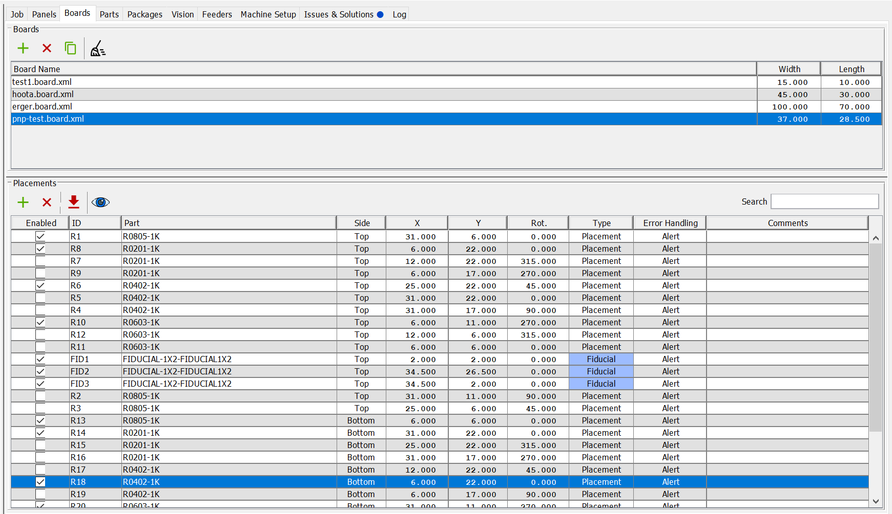
At the top of the Boards tab is a list of board definitions currently loaded into OpenPnP (they are not all necessarily part of the currently loaded job). You can create a new board definition or add an existing board definition to OpenPnP by clicking the button just above the list. You can remove one or more board definitions by selecting them in the list and clicking the
button. Removing a board definition from the list is only allowed if it is not in use by the current job or by any of the panel definitions currently loaded into OpenPnP. You can create a copy of a board definition by selecting it in the list and clicking the
button. This opens a dialog box allowing the copy to be saved to a new file name. This is useful for creating different variants of a board. Clicking the
![]() button removes all board definitions that are not in use by the current job or any panel definitions currently loaded into OpenPnP. Note, removing a board definition from OpenPnP does not delete the board definition from your file system so it can always be added again later.
button removes all board definitions that are not in use by the current job or any panel definitions currently loaded into OpenPnP. Note, removing a board definition from OpenPnP does not delete the board definition from your file system so it can always be added again later.
The columns shown in the Boards table are:
- Board Name: The name of the board definition.
- Width: The width of the board as measured in the direction of the X-axis of the board's coordinate system. This value is important for OpenPnP to correctly compute placement locations on the bottom side of the board. It is also used when graphical representations of the board are displayed.
- Length: The length of the board as measured in the direction of the Y-axis of the board's coordinate system. Currently this is only used when graphical representations of the board are displayed.
When a board is selected in the list, the table at the bottom of the tab shows the board's placements. Boards have their own coordinate system in which their placement locations are defined. This coordinate system is defined by your CAD software. Later, when using the board definition in either a job or panel definition, you will need to know where the origin of this coordinate system is located and how it is oriented with respect to the board. To that end, it is advisable when creating the board's design in your CAD software, to place the origin somewhere that is easy to recognize when viewed through the top camera. Typically, this will be the lower left corner of a rectangular board (when viewed from the top) with the positive X-axis to the right. See Understanding Board Locations for all the details.
The columns shown in the Placements table are:
- Enabled: Indicates whether or not this placement is active - only enabled placements will be placed. You can uncheck this if you don't want to place this placement. This is often referred to DNU (Do Not Use) or DNI (Do Not Install). Note, this setting can be overridden on an instance-by-instance basis from the Job tab.
- ID: All placements on a board must have a unique ID (regardless of side). These are usually the same as the reference designators you set when designing the PCB.
- Part: The part that should be placed at this location.
- Side: The board side on which the placement occurs. Can be set to either Top or Bottom.
- X, Y, Rot.: The coordinates of the placement relative to the board's coordinate system. The X and Y coordinates are measured viewing the board from its top side regardless of which side of the board the placement is located. Rotation is measured positive in the counterclockwise direction when viewing the placement from the side of the board the placement is located (note, this is probably different than the convention used by your CAD software but that is ok - the board importers take care of setting the angles correctly).
- Type: Sets the type of the placement to either Placement (meaning a part is to be placed here) or Fiducial (meaning it is only for visual reference).
- Error Handling: Sets the recommended action to take if an error occurs during a job when this placement is being placed. Can be set to either Alert (meaning to pause the job and wait for the operator to take action) or Defer (meaning to skip the placement and to continue the job). Note, this setting can be overridden on an instance-by-instance basis from the Job tab.
- Comments: A freeform text field that can contain any user definable text.
Placements are usually added to a board definition by clicking the ![]() button just above the placements table to import placement data from your CAD software. After the import is finished, check the list of placements and make any corrections - typically fiducials will need to have their type changed from Placement to Fiducial. Placements can also be added manually by clicking the
button just above the placements table to import placement data from your CAD software. After the import is finished, check the list of placements and make any corrections - typically fiducials will need to have their type changed from Placement to Fiducial. Placements can also be added manually by clicking the button and filling out the different fields appropriately. Placements can be deleted by selecting one or more in the table and clicking the
button. Clicking the
![]() button opens the Board Viewer that displays a graphical layout of the placements on the board.
button opens the Board Viewer that displays a graphical layout of the placements on the board.
If one or more Placements are selected in the Placements table, right-clicking on any of the selected placements opens a pop-up menu that allows the side, type, enabled status, or error handling action of all the selected Placements to be changed in one user action.
Panel definitions are the "blueprints" that tell OpenPnP how boards and/or subpanels are arranged to form a panel. Panel definitions are stored in files with the extension .panel.xml.
Setting up panel definitions is strictly optional. If you do not use panels, you can safely ignore them.
Panel definitions are typically created on the Panels tab.

At the top of the Panels tab is a list of panel definitions currently loaded into OpenPnP (they are not all necessarily part of the currently loaded job). You can create a new panel definition or add an existing panel definition to OpenPnP by clicking the button just above the list. You can remove one or more panel definitions by selecting them in the list and clicking the
button. Removing a panel definition from the list is only allowed if it is not in use by the current job or by any of the other panel definitions currently loaded into OpenPnP. You can create a copy of a panel definition by selecting it in the list and clicking the
button. This opens a dialog box allowing the copy to be saved to a new file name. This is useful for creating different variants of a panel. Clicking the
![]() button removes all panel definitions that are not in use by the current job. Note that removing a panel definition from OpenPnP does not delete the panel definition from your file system so it can always be added again later.
button removes all panel definitions that are not in use by the current job. Note that removing a panel definition from OpenPnP does not delete the panel definition from your file system so it can always be added again later.
The columns shown in the Panels table are:
- Panel Name: The name of the panel definition.
- Width: The width of the panel as measured in the direction of the X-axis of the panel's coordinate system. This value is important for OpenPnP to correctly compute placement locations on the bottom side of the panel. It is also used when graphical representations of the panel are displayed.
- Length: The length of the panel as measured in the direction of the Y-axis of the panel's coordinate system. Currently this is only used when graphical representations of the panel are displayed.
When a Panel is selected in the list, the middle table of the tab shows the panel's children. These are the boards and/or subpanels that make up the panel. Similar to boards, Panels also have their own coordinate system in which the location and orientation of their children (and the panel's fiducials, if any) are defined. And, as with boards, it is highly recommended that the origin of the Panel be placed somewhere that is easy to recognize when viewed through the top camera. Typically, this will be the lower left corner of a rectangular panel (when viewed from the top) with the positive X-axis to the right. See Panel Definitions for all the details.
The columns shown in the Children table are:
- Board/Panel ID: This is a user defined identifier for the child. This needs to be unique for each child of a panel.
- Name: This is the name of the child's definition. This value is set when the child is added to the panel. It can be changed by right-clicking on the child and selecting the Replace child(ren)... option from the pop-up menu.
- Width: This is the width of the child - this value is taken from the child's definition and is not editable here.
- Length: This is the length of the child - this value is taken from the child's definition and is not editable here.
- Side: This field defines which side of the child faces the top side of the panel.
- X, Y, Rot.: These fields define the coordinates and rotation of the child relative to the panel's coordinate system. They work similar as they do when defining the location and rotation of boards in a job.
- Enabled?: This indicates whether or not the child will have parts placed on it during a job. Note, this setting can be overridden on an instance-by-instance basis from the Job tab.
- Check Fids?: This indicates whether or not fiducials on the child will be checked during a job. Note, this setting can be overridden on an instance-by-instance basis from the Job tab.
There are a couple of options for adding children to a panel definition. A board or panel (known as a subpanel) can be manually added to the panel definition by clicking the button just above the list and editing the fields in the table appropriately. Arrays of boards or subpanels can be generated and added to the panel by selecting a single child in the table (this child will be replicated multiple times to create the array) and clicking the
![]() button. This opens a dialog that allows the number of rows and columns as well as the spacing of the rows and columns to be defined, see Creating Arrays for additional information. Children can be deleted by selecting one or more in the Children table and clicking the
button. This opens a dialog that allows the number of rows and columns as well as the spacing of the rows and columns to be defined, see Creating Arrays for additional information. Children can be deleted by selecting one or more in the Children table and clicking the button. Clicking the
![]() button opens the Panel Viewer that displays a graphical layout of the panel showing its children and fiducials.
button opens the Panel Viewer that displays a graphical layout of the panel showing its children and fiducials.
If one or more children are selected in the Children table, right-clicking on any of the selected children opens a pop-up menu that allows the children's definition, side, enabled status, or check fiducial status of all the selected children to be changed in one user action.
At the bottom of the Panels tab is a table showing the selected panel's fiducials. A panel can have dedicated fiducials to use for aligning it on the machine or it may use the fiducials located on its children (with respect to the panel, these are referred to as pseudo-fiducials). Even without fiducials, a panel can be aligned on the machine by using the manual multi-placement alignment process on a selected set of the children's placements (with respect to the panel, these are referred to as pseudo-placements).
The columns shown in the Alignment Fiducials/Placements table are:
- Enabled: The enabled state of the fiducial/placement. Only enabled fiducials will be checked during an automated fiducial check.
- ID: The identifier of the fiducial/placement. This must be unique for each entry. For pseudo-fiducials/pseudo-placements, the identifier is automatically generated and is a path to the actual fiducial or placement. They have the form subPanelId⇒...⇒subPanelId⇒boardId⇒placementId.
- Part: The part for this fiducial/placement. For pseudo-fiducials/pseudo-placements, the part is copied from the board definition.
- Side: The side of the panel on which this fiducial is located. For pseudo-fiducials/pseudo-placements, the side is determined by the board definition and how the board sides are oriented with respect to the panel.
- X, Y, Rot.: The coordinates of the fiducial as measured in the panels coordinate system. For pseudo-fiducials/pseudo-placements, the coordinates are automatically computed from the board definition and how the board is oriented with respect to the panel.
A dedicated panel fiducial can be manually added to the panel by clicking the button just above the list and editing the fields in the table appropriately. Pseudo-fiducials or pseudo-placements can be added to the panel by clicking the
![]() button and following the instructions in the dialog box. Fiducials can be removed by selecting one or more in the list and clicking the
button and following the instructions in the dialog box. Fiducials can be removed by selecting one or more in the list and clicking the button.
If one or more items are selected in the Alignment Fiducials/Placements table, right-clicking on any selected item opens a pop-up menu which allows the side or enabled status to be changed on all selected items through one user action.
A job definition is a set of instructions that tells OpenPnP what physical boards and/or panels to assemble. The job definition consists of a list of one or more boards and/or panels, along with their locations, orientations, and other information. A job definition may contain any number of boards and/or panels and can include multiples of the same board and/or panel or multiple different boards and/or panels. Each entry in the job definition tells OpenPnP where to find one particular board or panel using machine coordinates. When the job is run, OpenPnP will process all of the placements for each board in the Job.
A new job definition is created from OpenPnP's mainframe menu by selecting File->New Job. The file menu also has options for opening recent jobs as well as saving them. Job definitions are stored in files with the extension .job.xml. The name of the currently open job definition is shown at the top of OpenPnP's frame. If an existing job definition is opened, all board and/or panel definitions required by the job will be loaded into OpenPnP as well.
The job definition is edited on the Job tab:

At the top of the Job tab is a table that lists all of the boards and panels that are in the currently open job definition.
The columns shown in the job table are:
-
Board/Panel ID: This is a unique identifier for each board and/or panel. The IDs for top-level boards and panels can be edited here but they must be unique. The IDs for boards and panels that are descendants of an upper-level panel are set by their parent's panel definition and are not editable here. Boards are shown with a
 icon and panels with a
 icon. The entries are indented to show the heritage of the board/panel.
 - Name: This is the name of the board or panel's definition and is not editable here.
- Width: This is the width of the board or panel. It is set by the board or panel's definition and is not editable here*.
- Length: This is the length of the board or panel. It is set by the board or panel's definition and is not editable here*.
- Side: This is the side of the board or panel that is facing up on the machine. The side can only be changed for top-level boards and panels, i.e., the side of boards and panels that are descendants of a higher-level panel can't be changed here (although changing the side of a top-level panel will automatically change the side of all of its descendants).
- X, Y, Z, Rot.: This is location of the board or panel in machine coordinates. This can only be changed for top-level boards and panels, i.e., the location of boards and panels that are descendants of a higher-level panel can't be changed here (although changing the location of a top-level panel will automatically change the location of all of its descendants). The X, Y, and Rotation coordinates are explained in great detail in Understanding Board Locations. The Z coordinate should be set to the Z coordinate of the nozzle tip when it is just barely touching the upper surface of the physical board when it is on the machine. Part height is added to this when placing a part so that the nozzle tip stops at the right height above the board.
- Enabled?: This tells OpenPnP whether or not to process the board or panel when the job is run. Disabling a panel also disables all of its descendants. Enabling a panel also enables all of its descendants that were previously enabled when the panel was disabled.
- Check Fids?: This tells OpenPnP whether or not to perform an automatic fiducial check on the board or panel at the start of a job.
*Actually, editing the width and length of a board directly from the Job tab is supported under limited conditions - these fields can be edited only if there are no other instances of the board definition in the job and it is at the top-level of the job (not part of a panel).
Boards and/or panels are added to the Job table by clicking the button just above the list. If the Recommended Workflow is being followed, all board and/or panel definitions required for the job will have already been created so use the Existing Board... or Existing Panel... submenu options. Alternatively, boards and/or panels without existing definitions can be added with the New Board... or New Panel... submenu options (new entries for these will be created on their respective tab and will require additional editing there to complete their definitions).
For each board or panel added to the job definition, use the dropdown menu to set the Side to match the side of the physical board or panel that is facing up on the machine.
The Z coordinate of the board or panel is set by jogging a nozzle tip somewhere over the board or panel, carefully lowering it until it just touches the top surface, and then clicking the button. It is possible to select multiple boards and/or panels in the table and simultaneously set the Z coordinate of all of them to the same value by touching the nozzle tip to one and clicking the
button.
The X, Y, and Rot. fields are normally set by jogging the top camera crosshairs over the appropriate spot (see Understanding Board Locations) on the physical board or panel, rotating them to match the orientation of the board, and then clicking the button.
To obtain a more precise location for the board or panel, a fiducial check (assuming the board or panel has fiducials) can be performed by clicking the
![]() button. Alternatively, if the board or panel does not have fiducials, multiple placements can be used for the same purpose. This is a manual process that is started by clicking the
button. Alternatively, if the board or panel does not have fiducials, multiple placements can be used for the same purpose. This is a manual process that is started by clicking the
![]() button. A series of instructions will appear below the camera view guiding the process.
button. A series of instructions will appear below the camera view guiding the process.
Clicking the
![]() button opens a viewer that displays a graphical representation of the boards and panels as they are laid-out on the machine.
button opens a viewer that displays a graphical representation of the boards and panels as they are laid-out on the machine.
If one or more items are selected in the job table, right-clicking on any of the selected items opens a pop-up menu that allows the side, enabled status, or check fiducial status of all the selected items to be changed in one user action.
When a single board or panel is selected in the job table, the lower half of the Job tab displays the list of placements for that board or panel.
The columns shown in the Placements table are:
- Enabled: Indicates whether or not this placement is active - only enabled placements will be placed (or in the case of fiducials, be checked during a fiducial check). Disable this if this placement should not be placed. This is often referred to DNU (Do Not Use) or DNI (Do Not Install). Note, changing this setting here only affects the placement on the specific board or panel that is selected in the job table - it does not change the setting for the placement on any other boards or panels in the job. If it is desired to change the setting for this placement on all boards in the job, make the change to the board or panel definition on its respective tab.
- ID: All placements on a board must have a unique ID (regardless of side). These are usually the same as the reference designators you set when designing the PCB. This value was set when the placement was created and added to the board or panel's definition and is not editable here.
- Part: The part that should be placed at this location. This value is set by the board or panel's definition and is not editable here*.
- Side: The board side on which the placement occurs. Can be set to either Top or Bottom. This value is set by the board or panel's definition and is not editable here*.
- X, Y, Rot.: The coordinates of the placement relative to the board or panel's coordinate system. The X and Y coordinates are measured viewing the board or panel from its top side regardless of which side the placement is located. Rotation is measured positive in the counterclockwise direction when viewing the placement from the side the placement is located. These values are set by the board or panel's definition and are not editable here*.
- Type: Sets the type of the placement to either Placement (meaning a part is to be placed here) or Fiducial (meaning it is only for visual reference). This value is set by the board or panel's definition and is not editable here*.
- Placed: Indicates whether the part has been placed or not. If this field is checked, OpenPnP assumes that the placement's location on the board is already occupied by a part and it will not attempt to place another part at that location. This field will be updated as the job runs. Note, this setting only applies to the placement on the specific board or panel that is selected in the job table - it does not apply to placements on any other boards or panels in the job.
-
Status: Shows the current status of the placement - can be one of Disabled (meaning the placement is disabled - that's ok assuming the placement shouldn't be placed), Missing Feeder (meaning no feeder is available to supply the part needed for this placement - use the
 button to create a new feeder), Missing Part (meaning a part has not been assigned for this placement - go to the board's definition on the Boards tab and add a part for this placement), Part Height (meaning the part's height has either not been set or is set to zero - go to the Parts tab and set the part height to the correct value), or Ready (meaning the placement is ready to be placed when the job is run). The goal is to have the status of all placements on all boards of the job be either Disabled or Ready prior to running the job.
 - Error Handling: Sets the action to take if an error occurs during a job when this placement is being placed. Can be set to either Alert (meaning to pause the job and wait for the operator to take action) or Defer (meaning to skip the placement and to continue with the rest of the job). Note, this setting can be overridden on an instance-by-instance basis from the Job tab.
- Comments: A freeform text field that can contain any user definable text. This value is set by the board or panel's definition and is not editable here*.
*Actually, adding, editing, and deleting placements directly from the Job tab is supported under limited conditions - these fields can be edited only if there is exactly one instance of the selected board in the job and it is at the top-level of the job (not part of a panel).
A new placement is added to the table by button just above the list. One or more placements can be deleted by selecting them in the table and then clicking the
button. Note, these buttons are only enabled if there is exactly one instance of the selected board in the job and it is at the top-level of the job (not part of a panel). If those conditions are not met, adding or deleting placements must be done on the Boards or Panels tabs.
If a single placement is selected in the table, the top camera can be moved over its location by clicking the button. Subsequent clicks on the
![]() button will select the next placement in the list and move the camera to its location. Similarly, the currently selected tool can be moved to the selected placement's location by clicking the
button will select the next placement in the list and move the camera to its location. Similarly, the currently selected tool can be moved to the selected placement's location by clicking the button.
Clicking the or
buttons set the placement's X, Y, and Rotation fields to that of the top camera's or the currently selected tool's location respectively. Note, these buttons are only enabled if there is exactly one instance of the selected board in the job and it is at the top-level of the job (not part of a panel). If those conditions are not met, setting the coordinates of the placement must be done on the Boards or Panels tabs.
Clicking the
![]() button opens the Feeders tab and selects the feeder that will supply the part for the placement or prompts the operator to create a feeder for the part if one doesn't exist.
button opens the Feeders tab and selects the feeder that will supply the part for the placement or prompts the operator to create a feeder for the part if one doesn't exist.
If one or more Placements are selected in the Placements table, right-clicking on any of the selected placements opens a pop-up menu that allows the type, side, placed status, enabled status, or error handling action of all the selected Placements to be changed in one user action.
Everything in OpenPnP eventually makes it way back to a part. A part is simply a record that tells OpenPnP about a unique part that you want to place on a board. In general, a part should refer to a specific manufacturer part number but not to a packaging type. For instance, a 10k 0603 5% resistor and a 10k 0603 1% resistor are two different parts, but a 10k 0603 5% resistor in cut tape, and a a 10k 0603 5% resistor in a reel are the same part. It's easiest to think of parts as the manufacturer part number you specify in your BOM.
Parts are picked from feeders, and placed on placements. The information in the parts tab is used to tell OpenPnP about the physical properties of the part, which OpenPnP uses to accurately place the part.

The fields in the table are:
- ID: A unique ID for the part. It's usually best to use the manufacturer part number here.
- Description: A user defined description of the part. You can use this field for informational purposes, or for your own identifiers.
- Height: The physical height of the part as measured with calipers, or found in a data sheet. Part height is important because it determines how high above the board OpenPnP will stop when placing the part. You should only need to measure the part height for a specific part once, and then you can refer to the part in as many boards as you like.
- Package: The package type of the part. Common packages are things like R0603, C0402, TQFP-32, QFN-48, etc. By setting a package you tell OpenPnP more about the part and this information can be used for computer vision tasks. Packages do not have a height, since many parts share the same package but have different heights. Package is also used to tell OpenPnP the shape of a fiducial for fiducial recognition. See Fiducials for more information.
- Speed %: By default all parts are placed at 100% of the speed of the machine. You can lower that number here if you find that certain parts slip while being moved. In general, heavier parts may need slower speeds.
Packages tell OpenPnP more information about a part's physical properties. You can specify how many and what shape of pads or pins the part has, and information about the size of it's body.

Packages are not currently used very much in OpenPnP, except for in fiducials. You can ignore them for the most part. For information about setting up fiducial packages see Fiducials.
Feeders are where OpenPnP goes to find parts to pick. OpenPnP supports many different types of feeders, and each type can be configured in many different ways.
Most machines will have one or two types of feeders installed, and may have a number of "virtual" feeders, which can be as simple a piece of cut strip taped to the bed of the machine. Some of the most common feeder types are:
- Drag Feeders: A simple feeder that holds SMT tape. The head of the machine is used to drag the tape forward to expost the next part.
- Strip Feeders: A "virtual" feeder that uses computer vision to find parts in a piece of cut tape mounted to the machine. This is the easiest feeder to get started with. All you need to do is use double sided tape to stick a strip of parts down.
- Tray Feeders: A "virtual" feeder that picks parts from a uniform array of parts. Many larger parts come in JEDEC matrix trays and OpenPnP can easily cycle through all the parts in the tray.
- Auto Feeders: An auto feeder is a mechanism that OpenPnP can command to feed a part. These types of feeders are typically used on commercial machines to feed parts very quickly and accurately.
You can see all the different types of feeders by clicking the button in the feeders tab.

Most feeders have a location that you configure. The location is where you want OpenPnP to go to pick the part. Feeder locations are simple locations. In general no math is applied. The location you set is where the nozzle will go to pick. The part height is not used here.

When you add a feeder you need to set the part that is installed in it. You can have multiple feeders feeding the same part. OpenPnP will use one until it's empty and then move on to the next one.
In general, you will need as many feeders as there are unique parts on your board. For instance, if your board has a 10k 0603 5% resistor, and an 0603 red LED you will need two feeders - one for each part. Note, though, that don't need a feeder for every placement. Even if your board have 100 0603 red LEDs, you just need to set up the feeder for that part once.
The fields in the feeder table are:
- Name: An informative name you assign to the feeder. For example, if you use drag feeders you might call one feeder "Drag Slot 1".
- Type: The type of the feeder which you select when you add it.
- Part: The part that this feeder feeds. You can easily select a new part if, for instance, you remove one reel from a feeder and install a different one.
- Enabled: Whether the feeder is enabled. A disabled feeder will not be considered when OpenPnP is looking for parts.
Feeders are a big topic all on their own. For more details, see the Feeders section of the Setup and Calibration Guide.
Now that we understand all the pieces of a job, let's put them all together. This is a basic outline of what you'll do when setting up a new job. Some of these points are things you'll do every time, but many will be the same across multiple runs of the same job, or even different jobs.
-
Select the Job tab and create a new Job by selecting Main Menu -> File -> New Job. The Boards and Pick and Place tables will clear giving you a clean slate to work on.
-
Click the Add Board
button to add either a new board or an existing one. The most common option here is to add a new board and then import data for it.
-
Select Main Menu -> File -> Import Board and select the type of board definition you want to import. You can learn more about importing in Importing Centroid Data.
-
OpenPnP will import the board, optionally creating part and package definitions for you. You can edit these definitions later if you need to specify more information.
-
Look in the placements table and check the status of the placements that were imported. Change the type of placements that are used for fiducials, or that should be ignored. The status field will tell you more information about what else you might need to setup before you can run the job.
-
Go to the parts tab and set part heights for any parts that are missing their height value. You only need to do this once per part.
-
Configure feeders for each part in the job. An easy way to do this is to click a placement and then click the feeder edit button
. OpenPnP will either open the feeder for you, or prompt you to create a new one.
-
Set the position of the board in the Job tab. You can use capture camera
to find it automatically or use the multi-placement manual process
.
For additional information on using fiducials, see Fiducials.
-
You'll need to set the Z position of the board, too. Touch the nozzle tip to the board and use capture nozzle
Those are the basic steps to setting up a job. Each person will find a workflow that works best for them. Some people prefer to import all their parts up front and then setup the job, and others will just import the job and touch up what is needed.
Once all your placements are showing Ready in the status field, it's time to start placing!
You run jobs from the Job tab. The Start, Pause
, Stop
, and Step
buttons let you control the job as it progresses. Pressing Start will start the job and if there are no errors the machine will run the job to completion and then stop automatically.
In depth information about job processing can be found here.
As the job progresses, you can see how it's going by looking at the status bar at the bottom of the main window.

The status bar show you how many total placements there are in the whole job, and for the selected board, and how many have been placed. The progress bar gives you an indication of the total progress of the job. To the left a text field shows information about what OpenPnP is doing at any given moment, and will give information about any errors that come up.
When a job is running and something goes wrong, OpenPnP will try to recover from the problem if it can. In many cases, though, OpenPnP will stop and ask you how to proceed. You'll see an error message like this:

Based on the error you can decide how you want to proceed:
- Pause Job: The job pauses, the error message goes away, and you can make changes in OpenPnP to try to fix the problem.
- Ignore and Continue: Ignore the problem and try to go to the next step.
- Skip: Skip the rest of the processing for this placement and move on to the next one.
- Try Again: Try the operation that failed again.
If you choose to pause the job, once you've solved the problem you can hit Start again to continue from where you left off.
The Machine Setup tab is both the most complex part of OpenPnP, and the most simple. Here you configure all the components that make up the machine. This configuration is what makes OpenPnP work with your specific machine.

The Machine Setup tab is a tree control with the root of the tree being the machine itself, and the branches and leaves of the tree being different things attached to the machine. You can setup cameras, feeders, nozzles, nozzle tips, job processing settings, and most importantly, the driver that lets OpenPnP talk to your machine controller.
As you click on different parts of the tree, the buttons under the tab will change to show options for that component. For instance, if you expand Heads and select Nozzles you can click the buttons above to add and remove nozzles. Clicking a nozzle let's you add nozzle tips to it, and so on.
The Setup and Calibration Guide is the best reference to the Machine Setup tab. It will guide you through setting up your own machine, but you should also consider clicking through the objects in the tree to get a feel for what options are present for each.
A common source of confusion is how OpenPnP uses the various Z values and Part heights throughout the system. In simplest terms:
- Parts are picked from feeders at the Z value specified on the feeder. Every feeder type has a Z value you can set, and this is where the nozzle will be lowered to before picking.
- Every board in a job has a location which includes a Z value. The Z value is the surface of the board facing up on the machine.
- Every part has an associated height value. The height value is added to the board's Z value when placing.
See Scripting for information about OpenPnP's built in scripting engine, which can be used to add new functionality to OpenPnP without changing the source code.
Configuration files are located in your home directory, under a subdirectory called .openpnp.
- On Mac this will typically be
/Users/[username]/.openpnp. - On Windows 2000, XP and 2003 it will be
C:\Documents and Settings\[username]\.openpnp. - On Windows Vista and above it's
C:\Users\[username]\.openpnp.
Configuration files are in XML format and can be edited by hand in a text editor. You should shutdown OpenPnP before editing files by hand as OpenPnP will rewrite the configuration files on exit.
There are three primary configuration files. They are:
-
machine.xml: Contains the primary configuration for the entire system, including information about the machine, cameras, feeders, nozzles, etc. -
parts.xml: A portable parts database. As you define parts (components) in OpenPnP they are stored here. -
packages.xml: A portable packages database. Component package information including shape and dimensions are stored here.
If you are interested in having OpenPnP work with a machine that is not currently supported
you will need an OpenPnP driver that can talk to your hardware and you will need to
configure it in the machine.xml.
To get started, look at the list of drivers in the package below to see what drivers are available and determine if one will meet your needs.
https://github.com/openpnp/openpnp/tree/develop/src/main/java/org/openpnp/machine/reference/driver
If none of those will work for your machine, you will need to write one. Once
you have a driver, you can specify it's classname and configuration parameters
in machine.xml.
See the Development section for more information if you decide you need to write code.
For more information about developing OpenPnP, especially regarding contributing, please see https://github.com/openpnp/openpnp/wiki/Developers-Guide.
There is an active discussion group at http://groups.google.com/group/openpnp. This will typically be the best place to get help.
We also have an IRC channel on Freenode IRC at #openpnp. If you don't have an IRC client, you can use this web based one.
 Search the Wiki