

Introduction: Arduino Controlled Robotic Biped

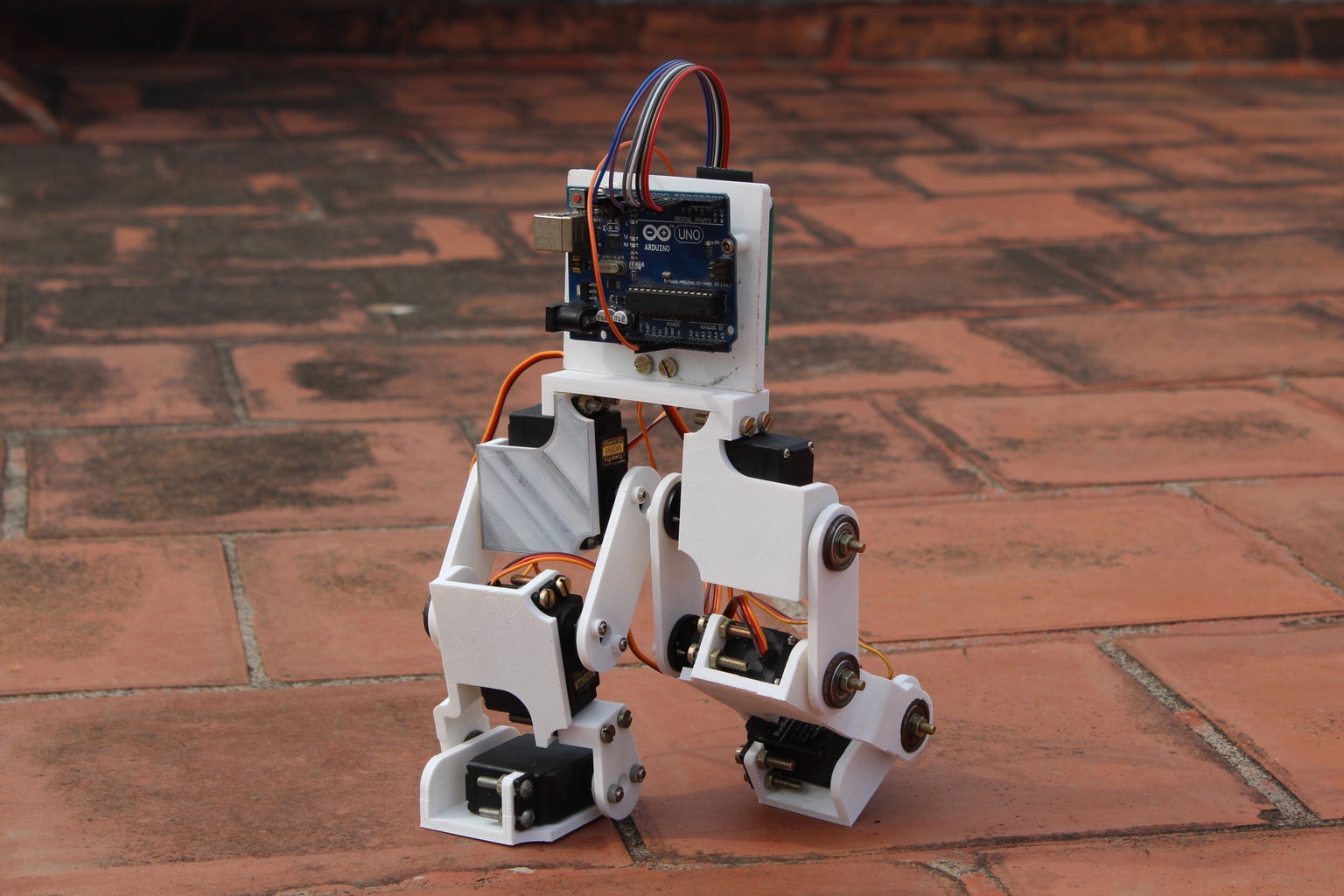


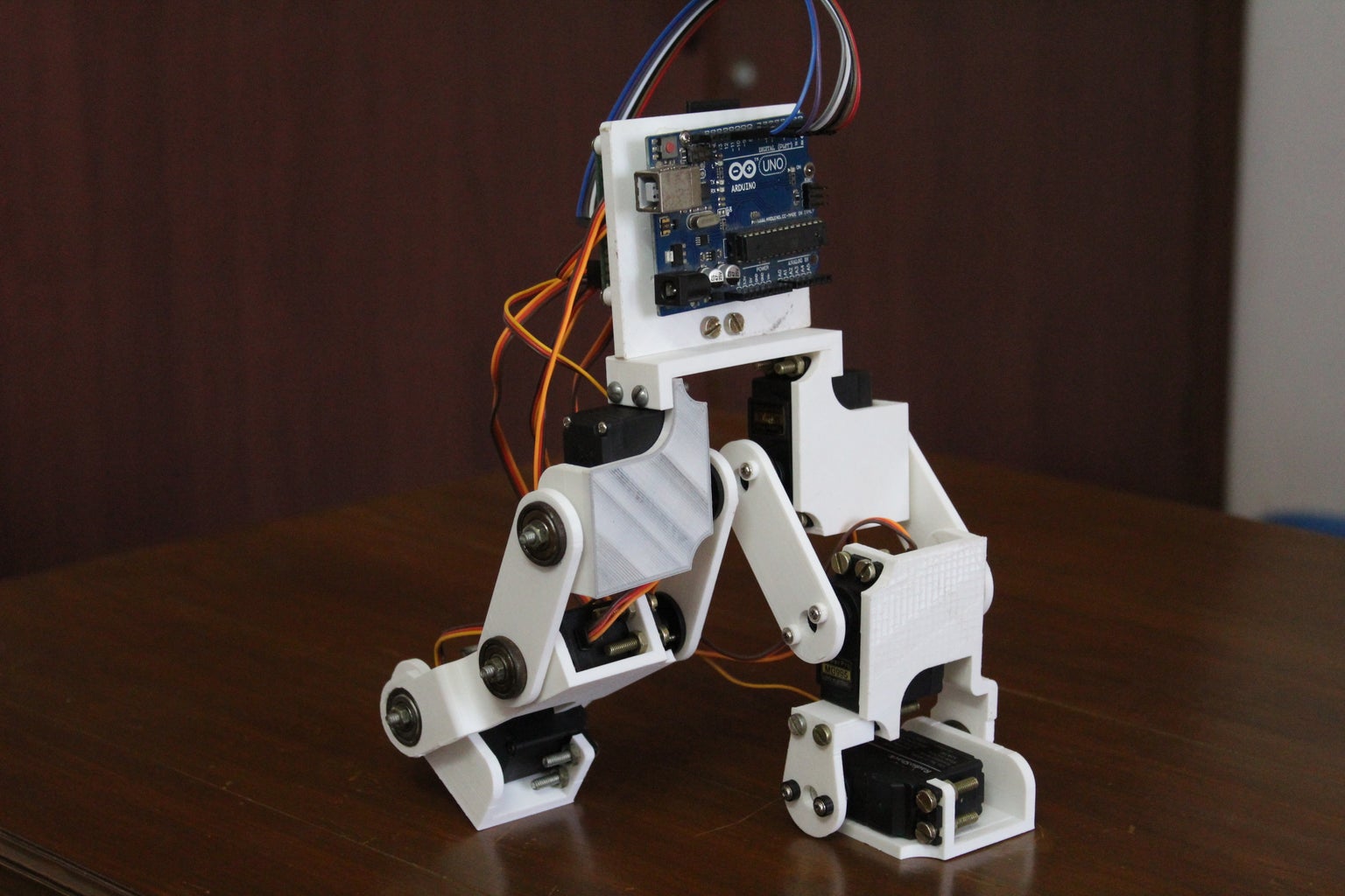


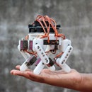

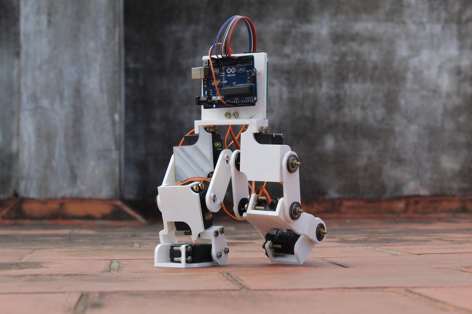
I have always been intrigued by robots, especially the kind that attempts to mimic human actions. This interest led me to try to design and develop a robotic biped that could imitate human walking and running. In this Instructable, I will show you the design and assembly of the robotic biped.
The primary goal while building this project was to make the system as robust as possible such that while experimenting with various walking and running gaits, I wouldn't have to constantly worry about the hardware failing. This allowed me to push the hardware to its limit. A secondary goal was to make the biped relatively low-cost using readily available hobby parts and 3D printing leaving room for further upgrades and expansions. These two goals combined provide a robust foundation to perform various experiments, letting one develop the biped to more specific requirements.
Follow on to create your own Arduino controlled Robotic Biped and do drop a vote in the "Arduino Contest" if you liked the project.
Step 1: Design Process
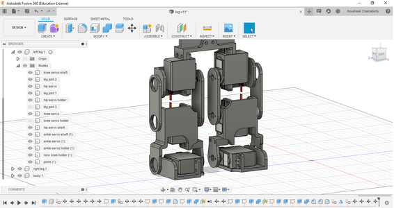
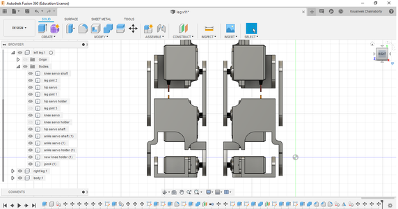
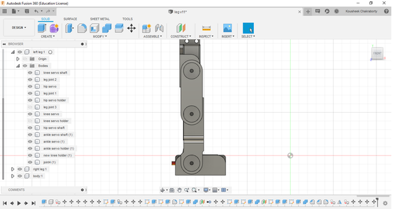
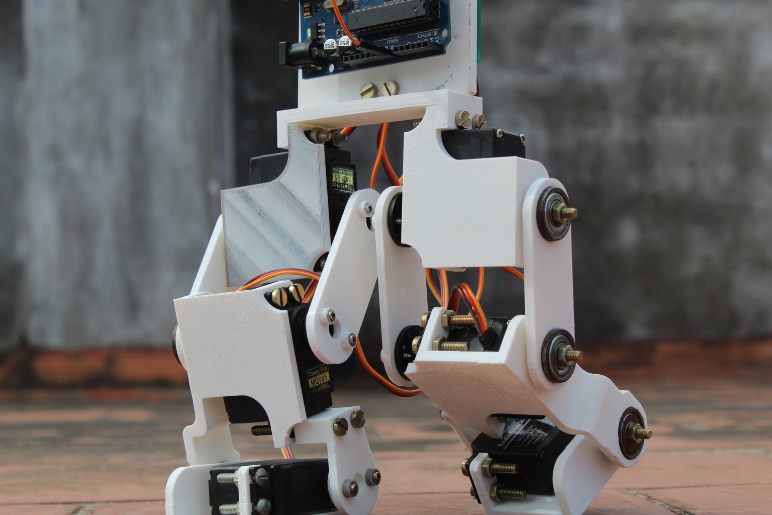
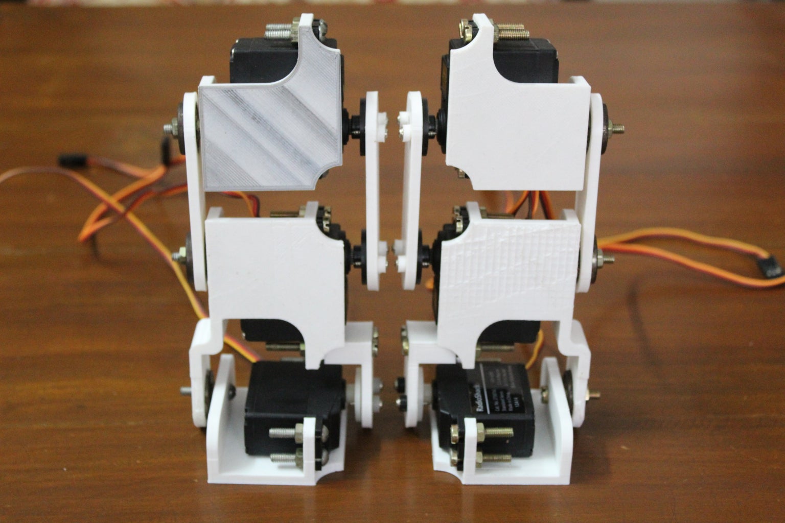
The humanoid legs were designed in Autodesk's free to use Fusion 360 3d modelling software. I began by importing the servo motors into the design and built the legs around them. I designed brackets for the servo motor which provides a second pivot point diametrically opposite to the servo motor's shaft. Having dual shafts on either end of the motor gives structural stability to the design and eliminates any skewing that may occur when the legs are made to take some load. The links were designed to hold a bearing while the brackets used a bolt for the shaft. Once the links were mounted to the shafts using a nut, the bearing would provide a smooth and robust pivot point on the opposite side of the servo motor shaft.
Another goal while designing the biped was to keep the model as compact as possible to make maximum use of the torque provided by the servo motors. The dimensions of the links were made to achieve a large range of motion while minimizing the overall length. Making them too short would make the brackets collide, reducing the range of motion, and making it too long would exert unnecessary torque on the actuators. Finally, I designed the body of the robot onto which the Arduino and other electronic components would mount.
Note: The parts are included in one of the following steps.
Step 2: The Role of the Arduino
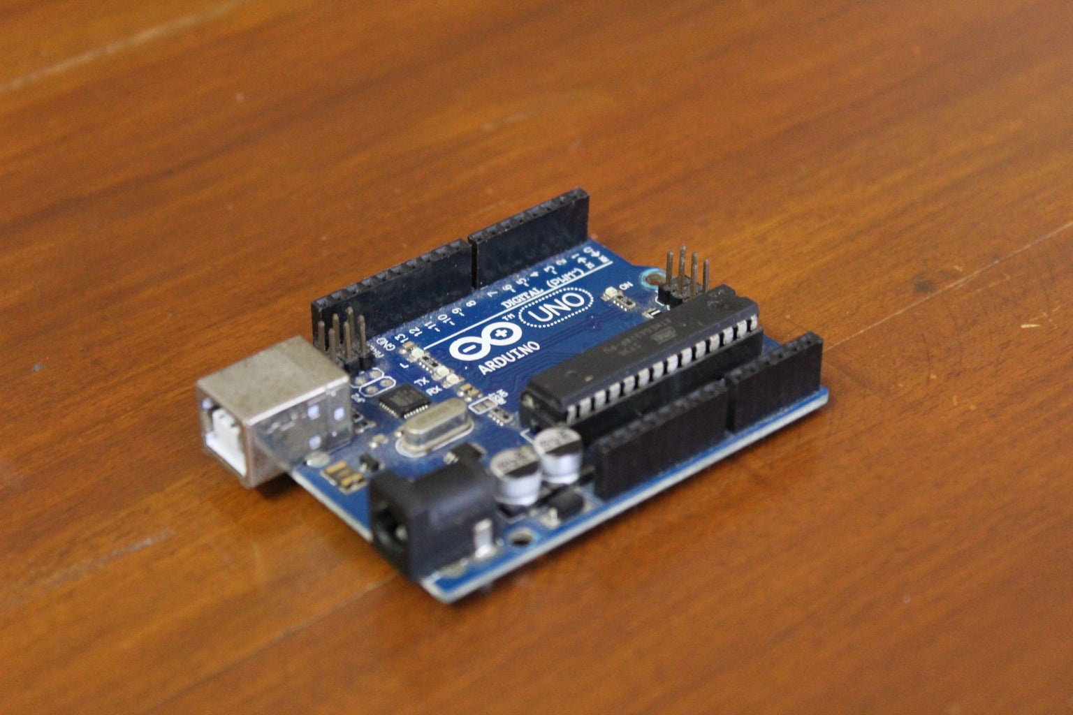
An Arduino Uno was used in this project. The Arduino was responsible to compute the motion paths of the various gaits that were tested and instructed the actuators to move to precise angles at precise speeds to create a smooth walking motion. An Arduino is a great choice for developing projects because of its versatility. It provides a bunch of IO pins and also provides interfaces such as serial, I2C, and SPI to communicate with other microcontrollers and sensors. The Arduino also provides a great platform for rapid prototyping and testing and also gives developers room for improvements and expandability. In this project, further versions will include an Inertial Measurement Unit for motion processing such as fall detection and dynamic locomotion in uneven terrain and a distance measuring sensor to avoid obstacles.
The Arduino IDE was used for this project. (Arduino also provides a web-based IDE)
Note: The programs for the robot can be downloaded from one of the following steps.
Step 3: Materials Needed
Here is the list of all the components and parts required to make your very own Arduino powered Bipedal robot. All parts should be commonly available and easy to find.
ELECTRONICS:
- Arduino Uno x 1
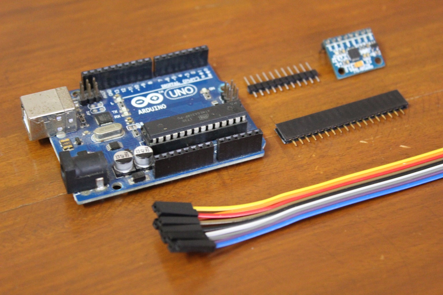
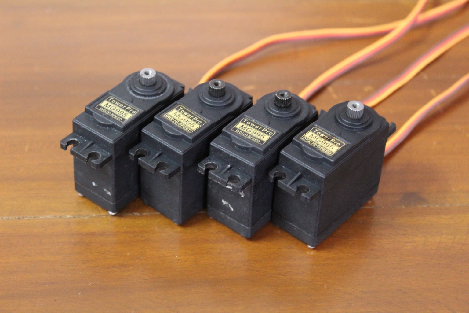
- Towerpro MG995 servo motor x 6
- Perfboard (similar size to the Arduino)
- Male and Female header pins (about 20 of each)
- Jumper Wires (10 pieces)
- MPU6050 IMU (optional)
- Ultrasonic sensor (optional)
HARDWARE:
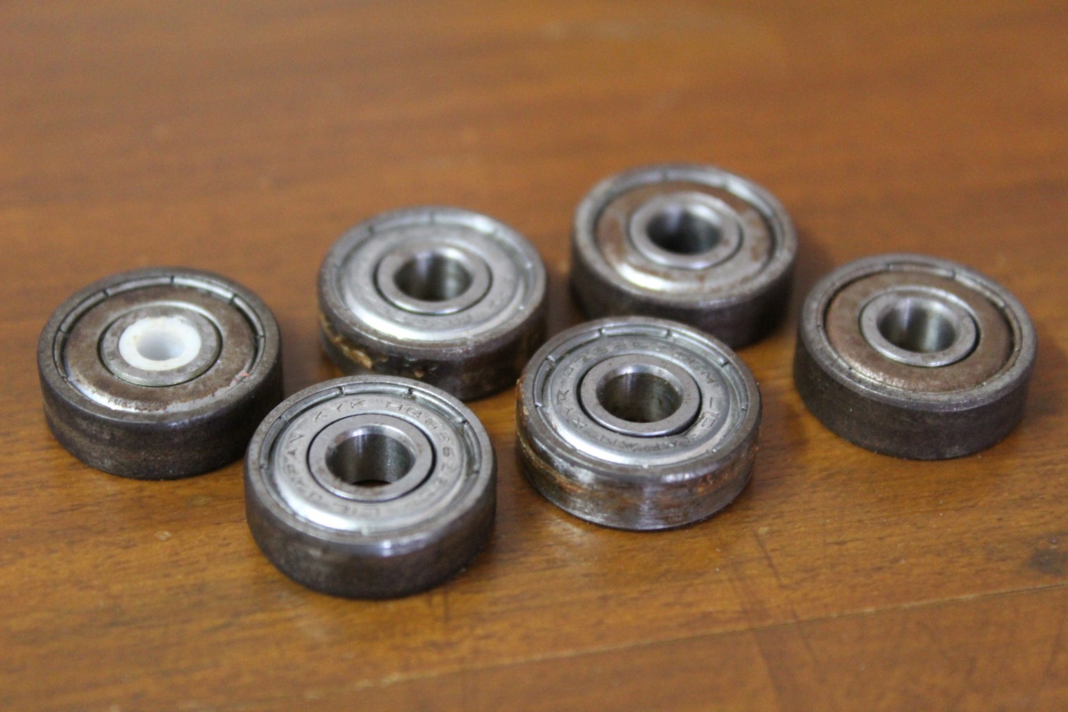
- Skateboard Bearing (8x19x7mm)
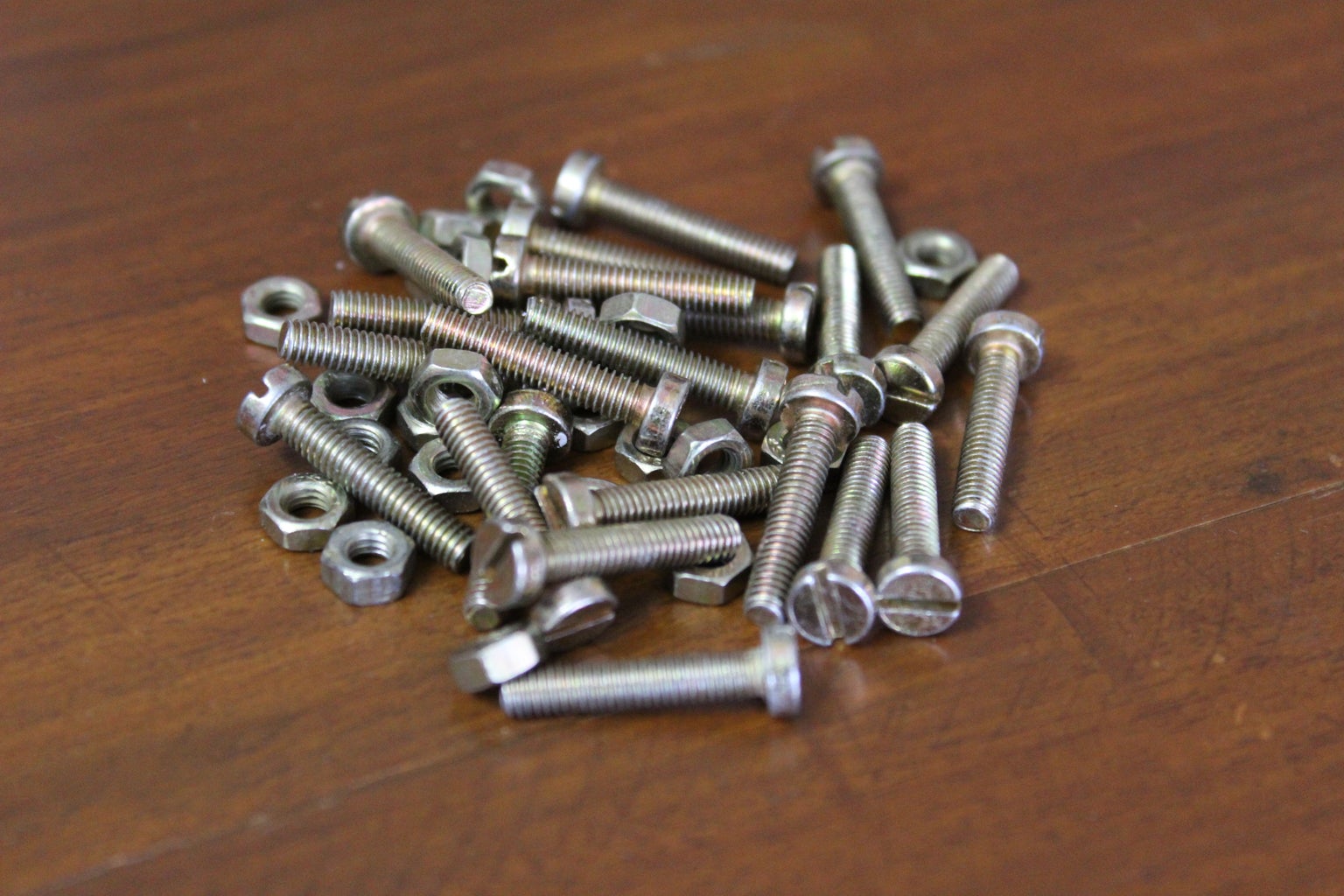
- M4 nuts and bolts
- 3D printer filament (in case you don't own a 3D printer, there should be a 3D printer in a local workspace or the prints can be done online for quite cheap)
Excluding the Arduino and 3D printer the total cost of this project is 20$.
Step 4: 3D Printed Parts


The parts required for this project had to be custom designed therefore a 3D printer was used to print them out. The prints were made at 40% infill, 2 perimeters, 0.4mm nozzle, and a layer height of 0.1mm with PLA, color of your choice. Below you can find the complete list of parts and the STLs to print your own version.
Note: From here on the parts will be referred to using the names in the list.
- foot servo holder x 1
- foot servo holder mirror x 1
- knee servo holder x 1
- knee servo holder mirror x 1
- foot servo holder x 1
- foot servo holder mirror x 1
- bearing link x 2
- servo horn link x 2
- foot link x 2
- bridge x 1
- electronics mount x 1
- electronics spacer x 8 (optional)
- servo horn space x 12 (optional)
In total, excluding the spacers, there are 14 parts. The total printing time is about 20 hours.

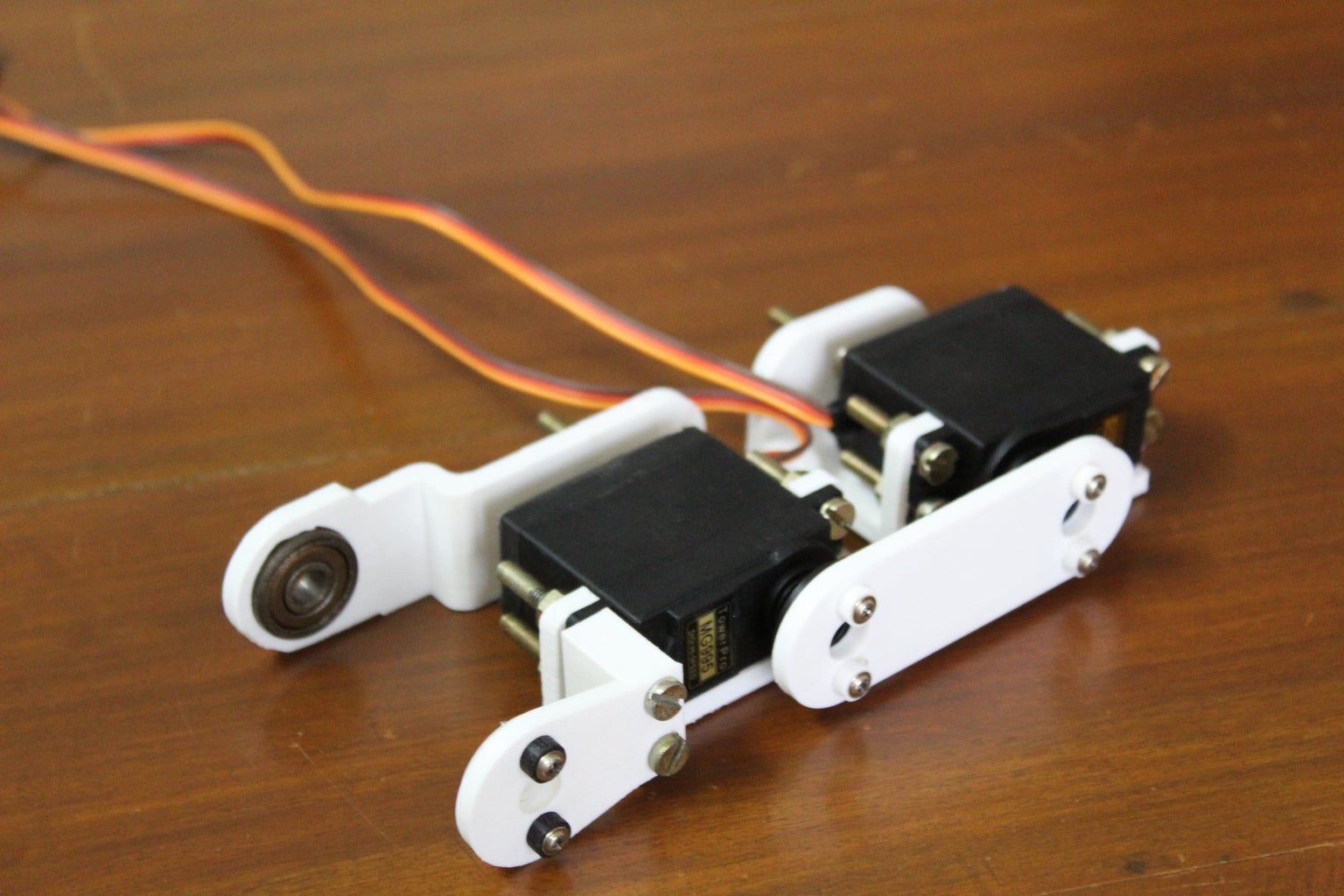
Step 5: Preparing the Servo Brackets

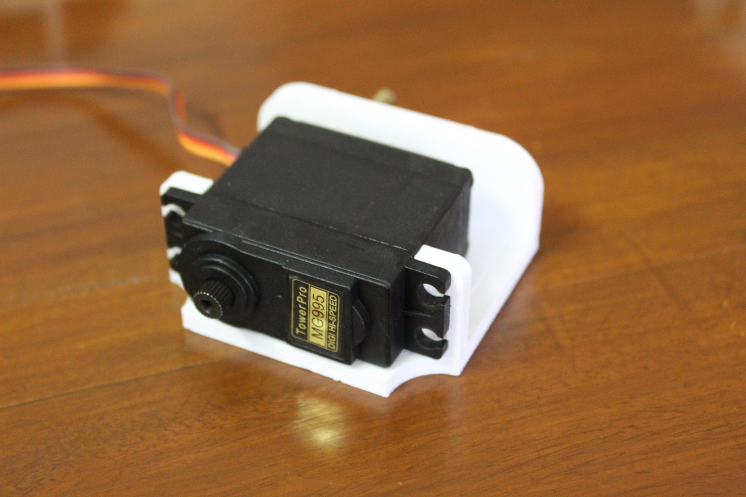

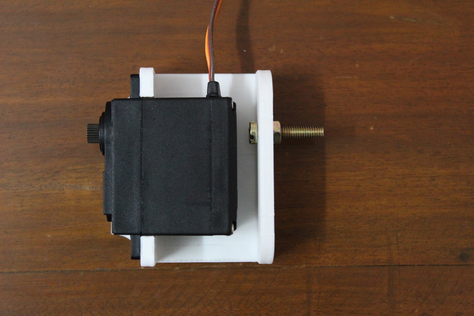
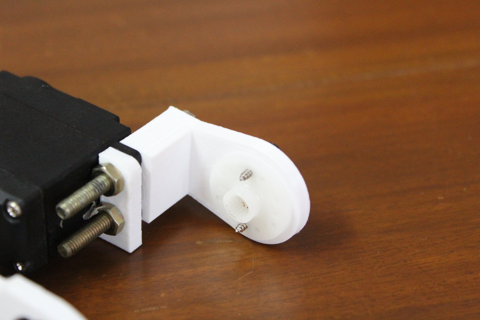
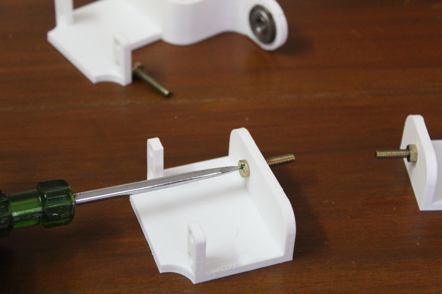


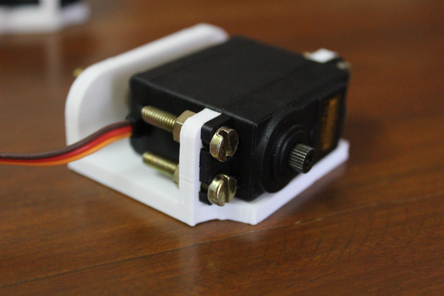
Once all of the parts are printed you can begin by setting up the servos and the servo brackets. First push in a bearing into the knee servo holder. The fit should be snug but I would recommend sanding the inner surface of the hole a bit instead of forcing the bearing which may risk breaking the part. Then pass an M4 bolt through the hole and tighten it using a nut. Next, grab the foot link and attach a circular servo horn to it using the supplied screws. Attach the foot link to the knee servo holder using the screws you will use to also attach the servo motor. Make sure to align the motor so that the shaft is on the same side of the bolt you had attached earlier. Finally secure the servo with the rest of the nuts and bolts.
Do the same with the hip servo holder and foot servo holder. With this, you should have three servo motor and their corresponding brackets.
Note: I am providing instructions for building one leg, the other is simply mirrored.
Step 6: Making the Link Pieces

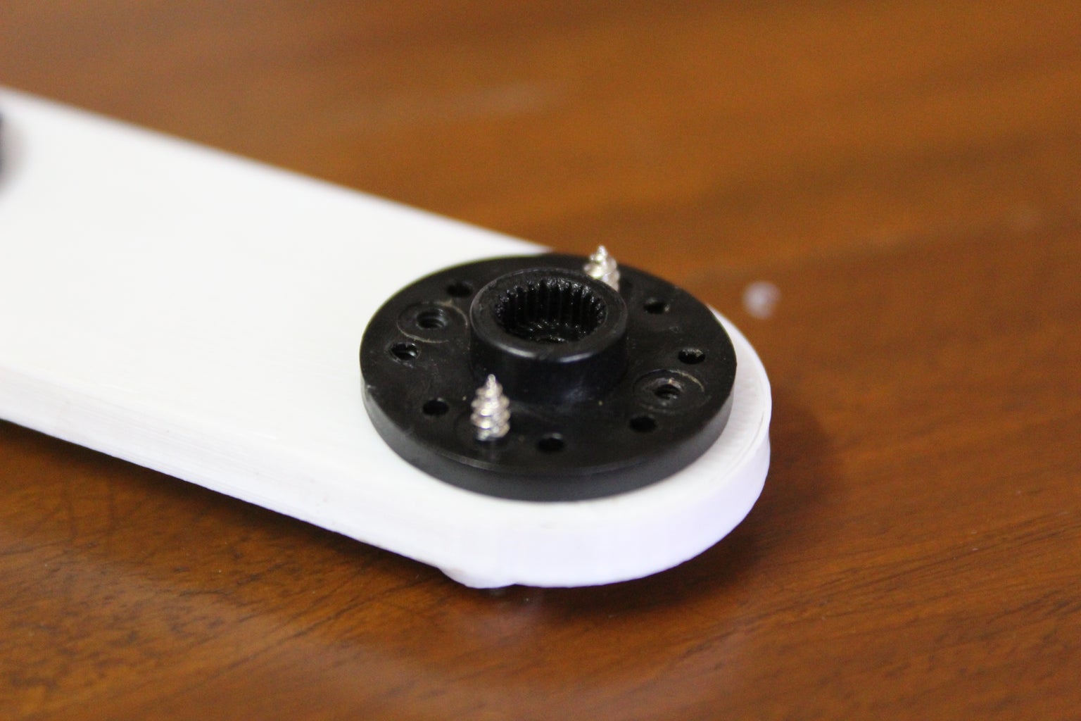


Once the brackets are assembled, start making the links. To make the bearing link, once again lightly sand the inner surface of the holes for the bearing then push the bearing into the hole on both sides. Make sure to push the bearing in till one side is flush. To build the servo horn link, grab two circular servo horns and the supplied screws. Place the horns on the 3D print and line up the holes, next screw the horn onto the 3D print by attaching the screw from the 3D print side. I recommend using a 3D printed servo horn spacer for these screws. Once the links are built you can begin the assemble the leg.
Step 7: Assembling the Legs
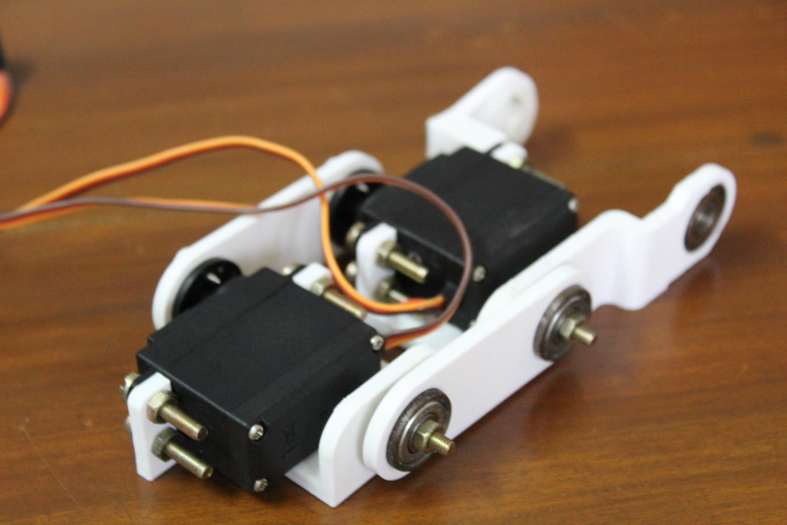

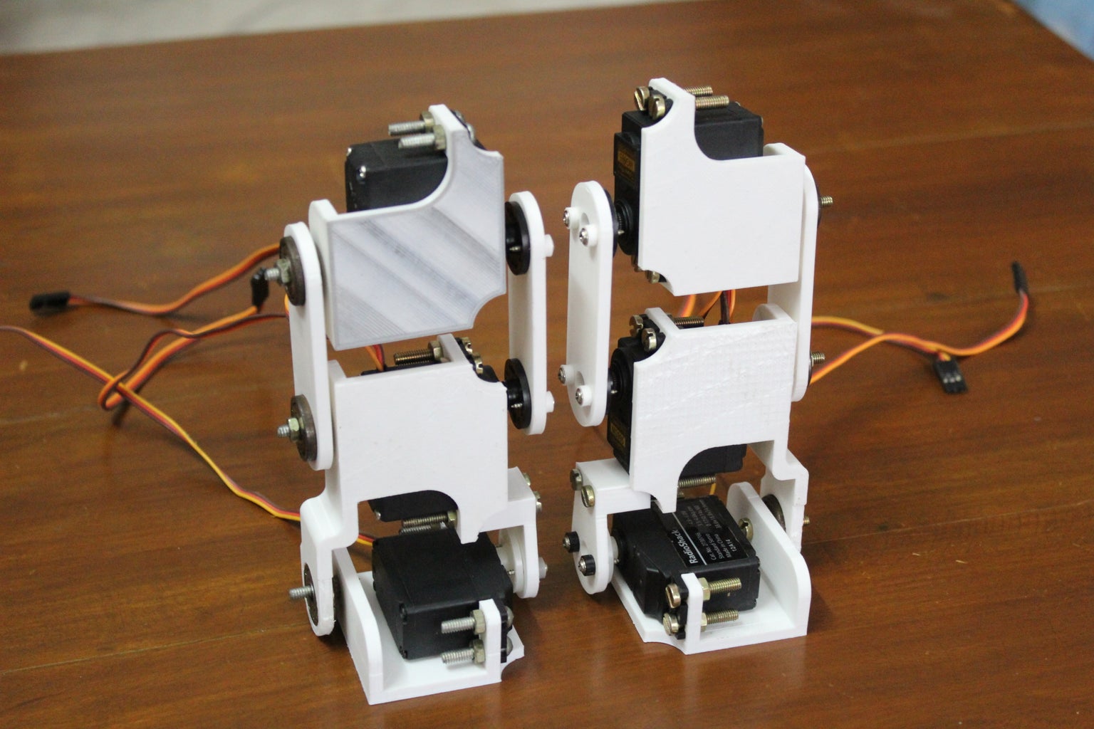
Once the links and brackets are assembled, you can combine them to build the leg of the robot. First, use the servo horn link to attach the hip servo bracket and knee servo bracket together. Note: Don't screw the horn to the servo just yet as there is a setup stage in the following stage and it'll be an inconvenience if the horn were screwed onto the servo motor.
On the opposite side mount the bearing link onto the protruding bolts using nuts. Lastly, attach the foot servo bracket by inserting the protruding bolt through the bearing on the knee servo holder. And fix the servo shaft to the servo horn connected to the knee servo holder on the other side. This may be a tricky task and I would recommend a second pair of hands for this.
Repeat the steps for the other leg. Use the pictures attached to each step as a reference.
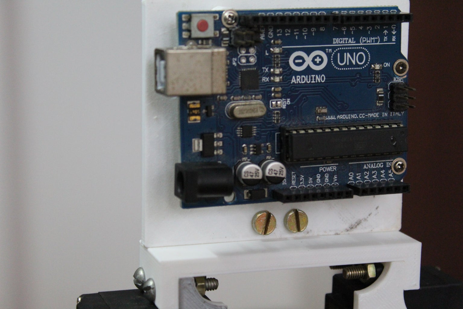
Step 8: Custom PCB and Wiring
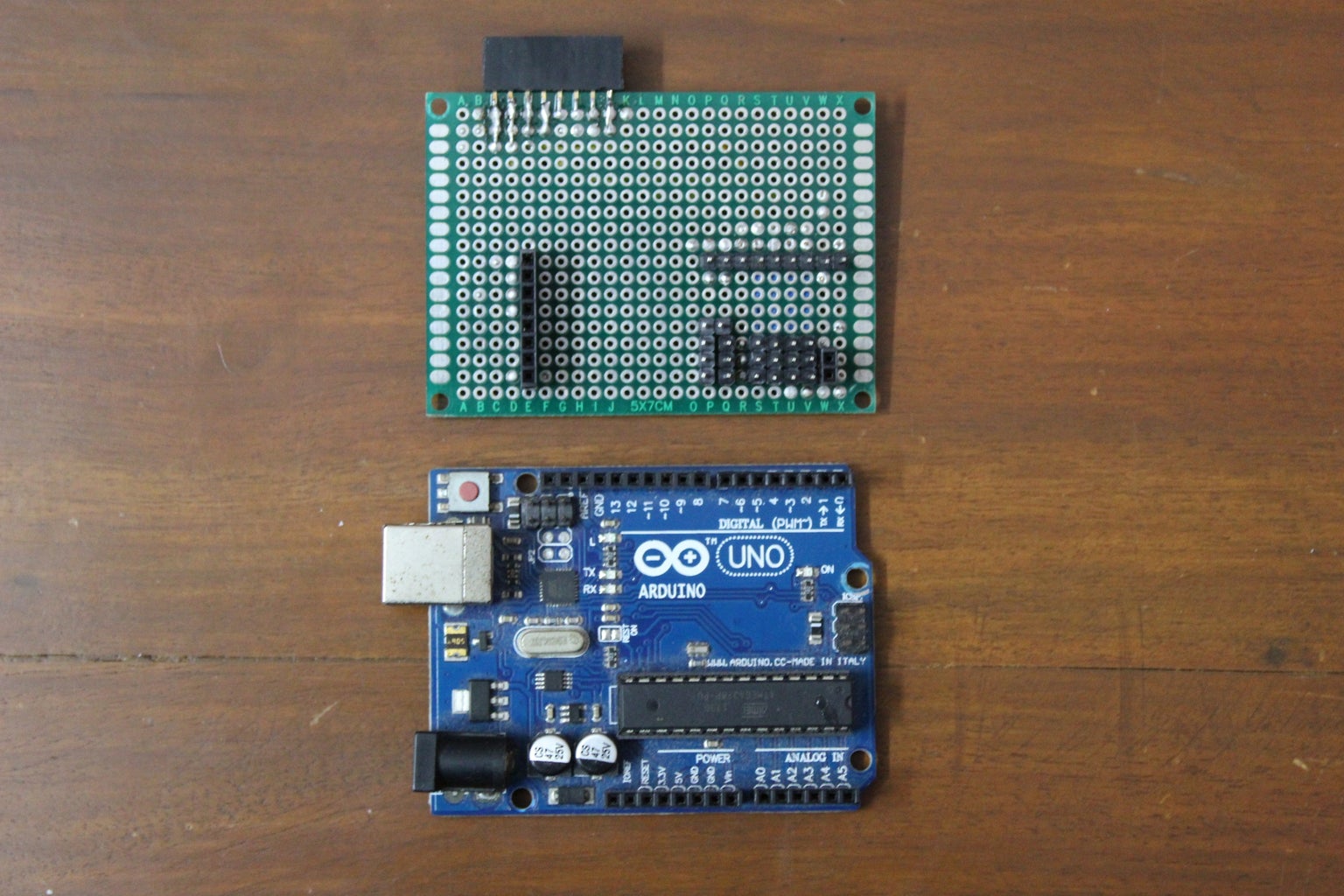

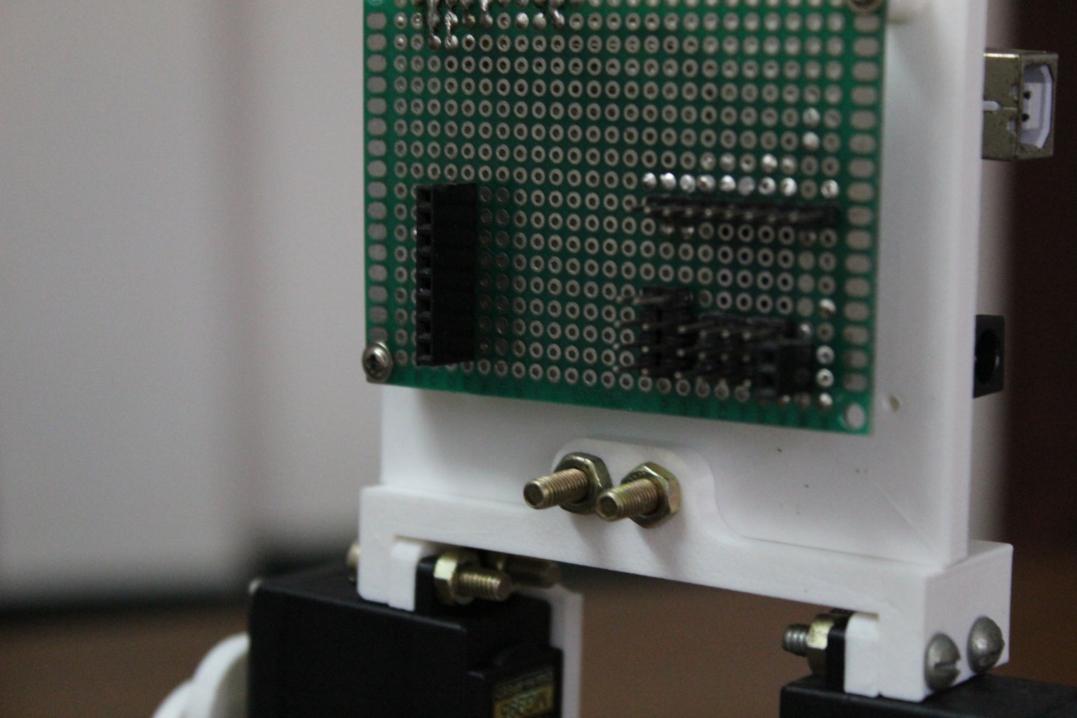
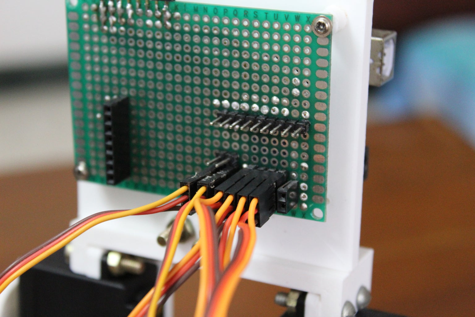
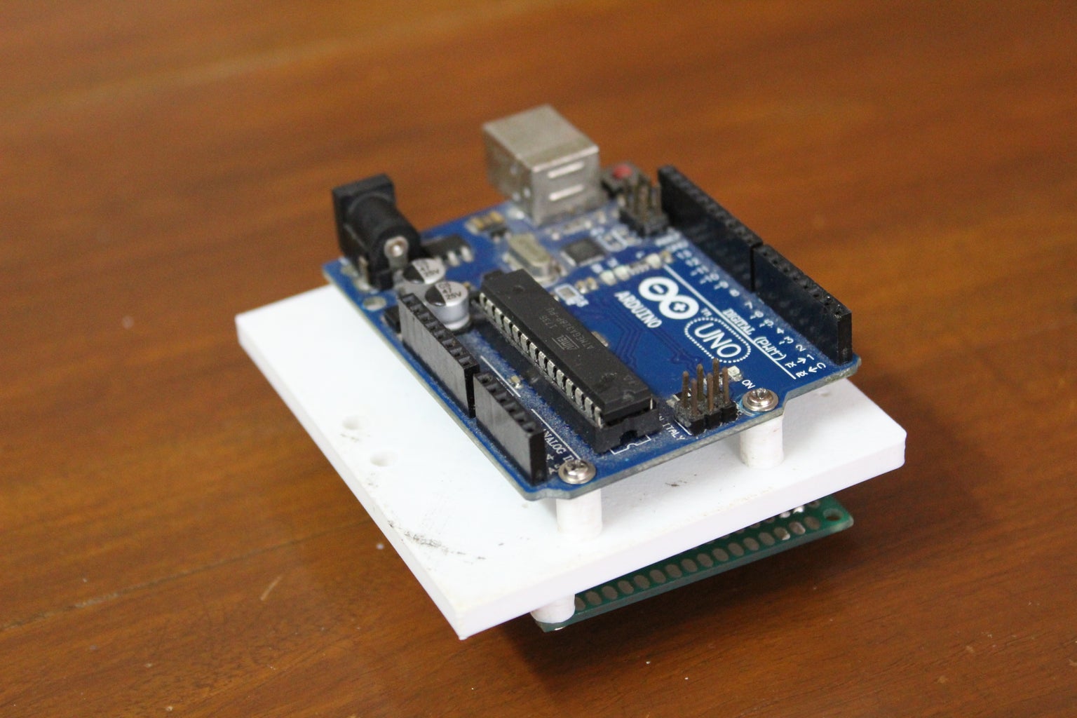
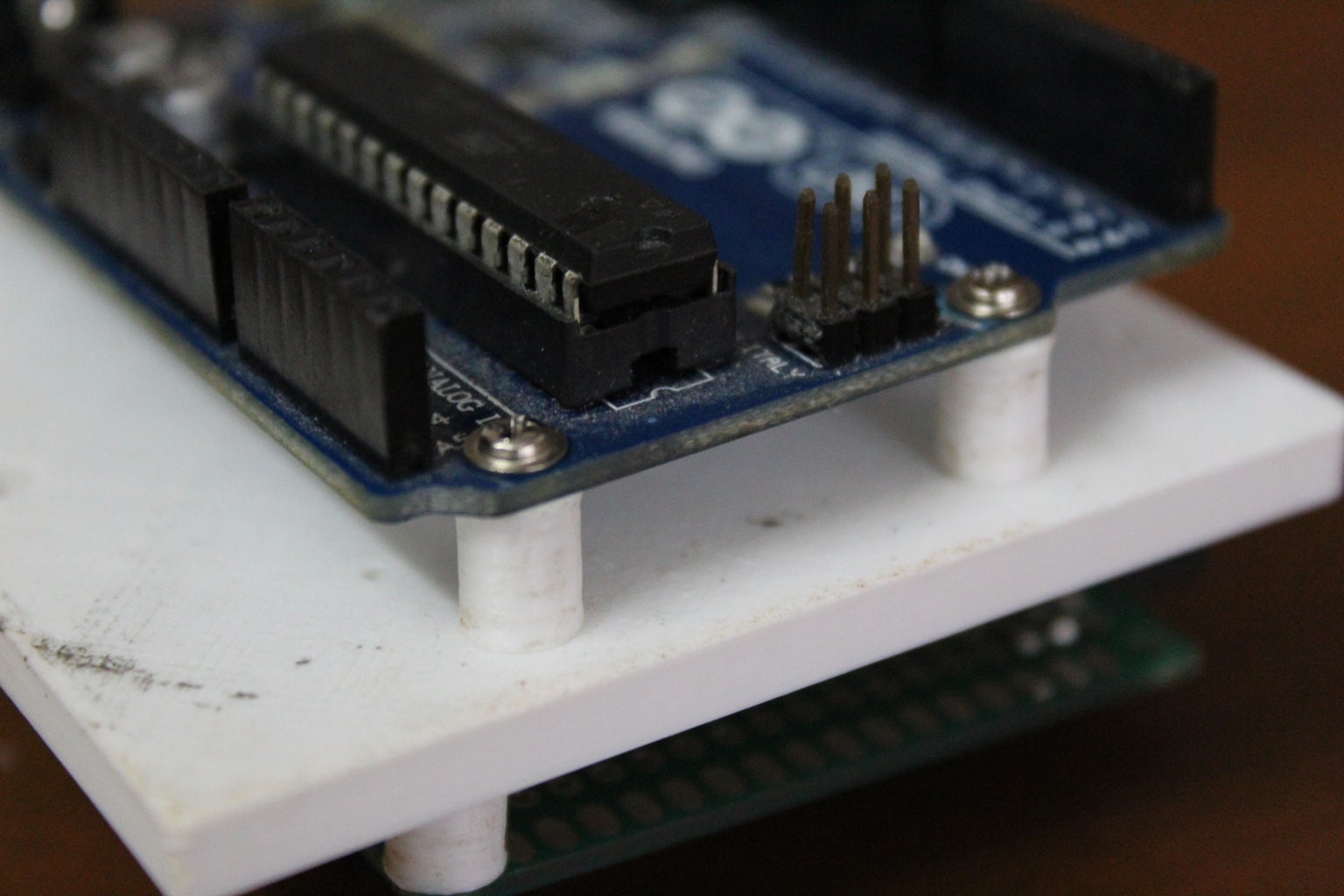

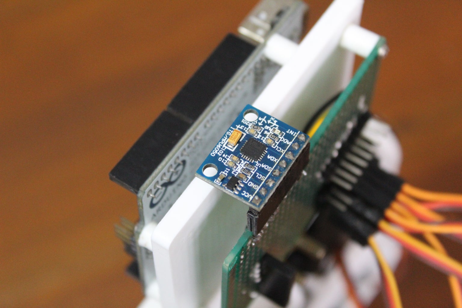
This is an optional step. To make the wiring neater I decided to make a custom PCB using perf board and header pins. The PCB contains ports to directly connect the servo motor wires. In addition, I also left extra ports in case I wanted to expand and add other sensors such as Inertial Measurement Units or ultrasonic distance sensors. It also contains a port for the external power source required to power the servo motors. A jumper connection is used to switch between USB and external power for the Arduino. Mount the Arduino and PCB to either side of the electronics mount using screws and the 3D printed spacers.
Note: Make sure to unplug the jumper before connecting the Arduino to your computer through USB. Not doing this may result in damaging the Arduino.
If you decide to not use the PCB and instead use a breadboard here are the servo connections:
- Left Hip >> pin 9
- Right Hip >> pin 8
- Left Knee >> pin 7
- Right Knee >> pin 6
- Left Foot >> pin 5
- Right Foot >> pin 4
If you do decide to make the PCB follow the same order as above by using the ports on the PCB from right to left with the IMU port facing up. And use regular male to female jumper wires to connect the PCB to the Arduino using the above pin numbers. Make sure to also connect the ground pin and create the same ground potential and Vin pin for when you decide to run it without USB power.
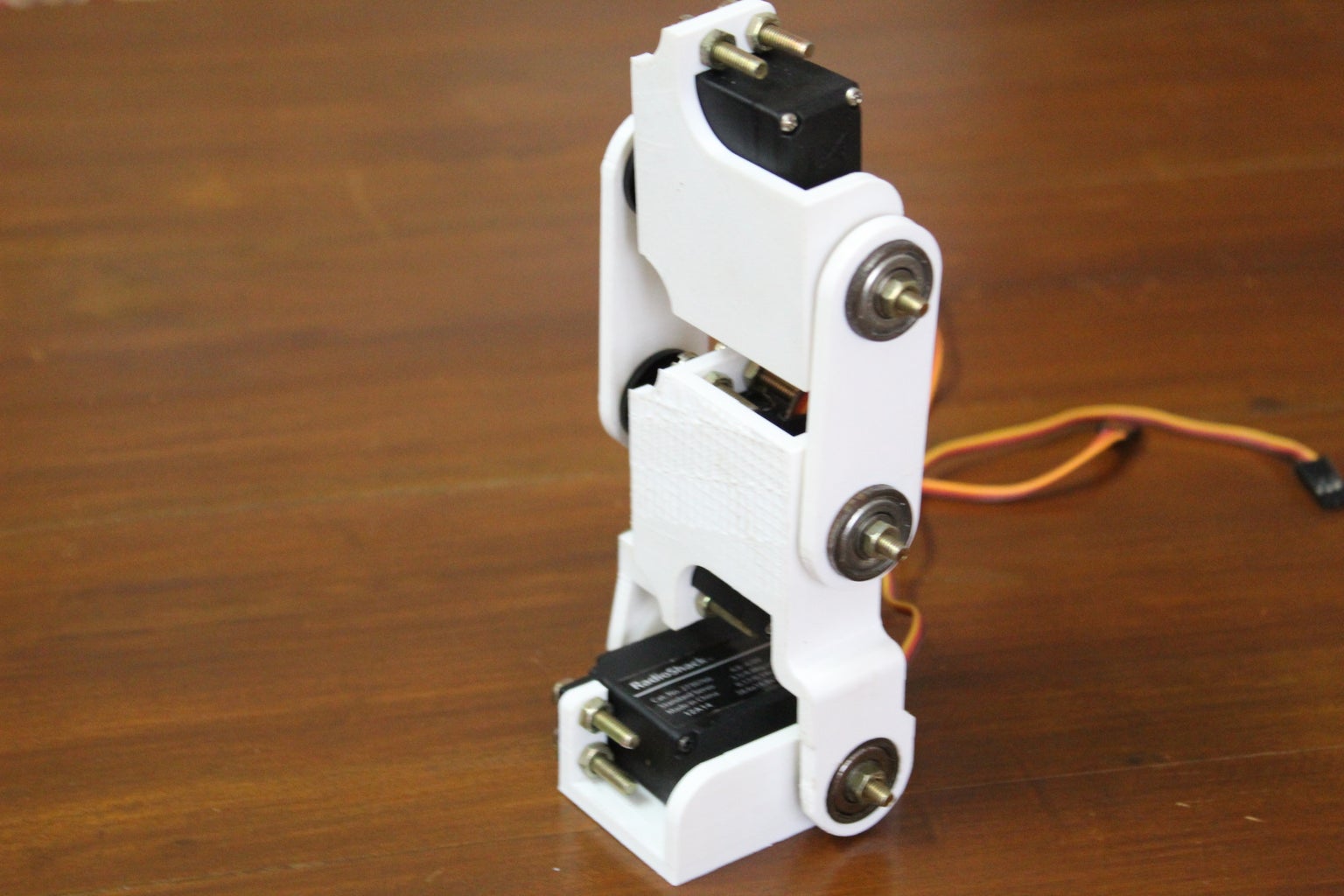
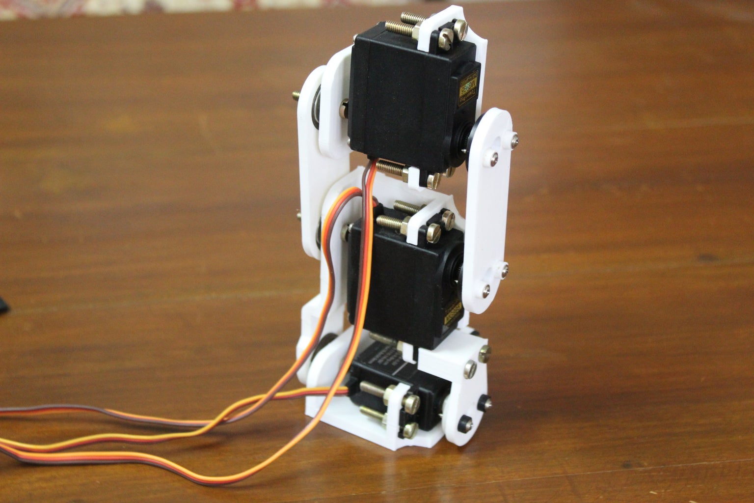
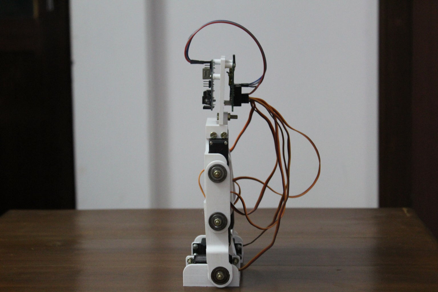
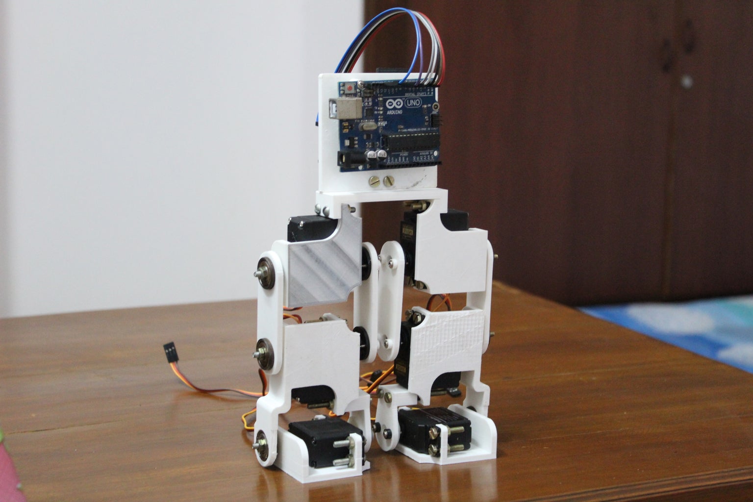
Step 9: Assembling the Body


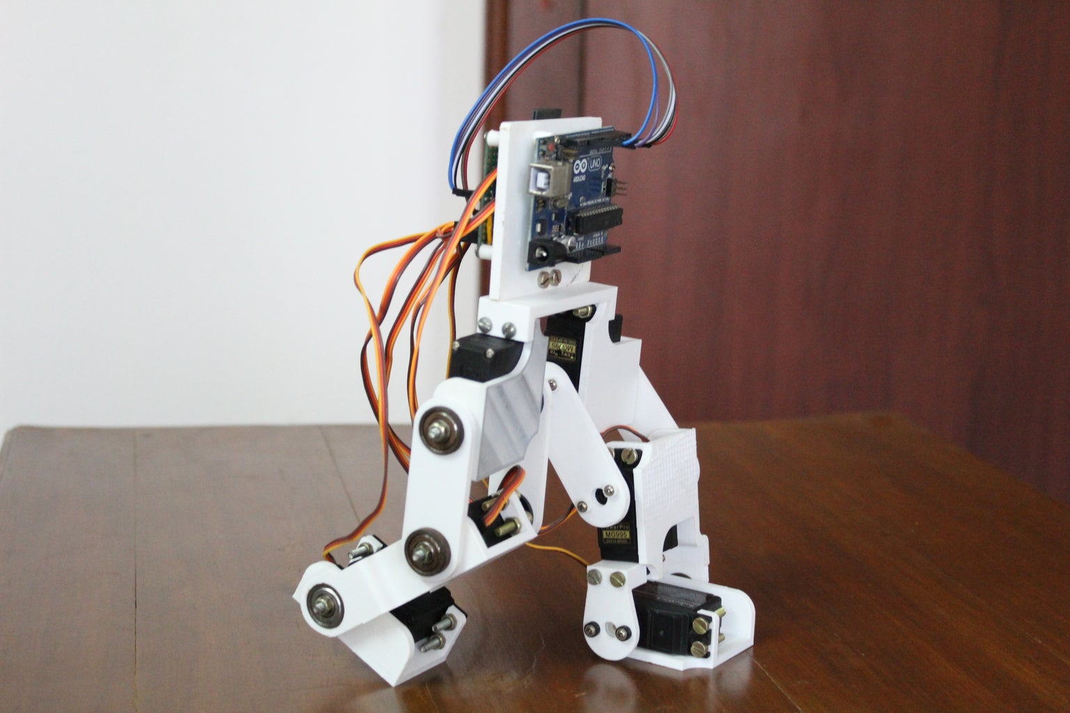
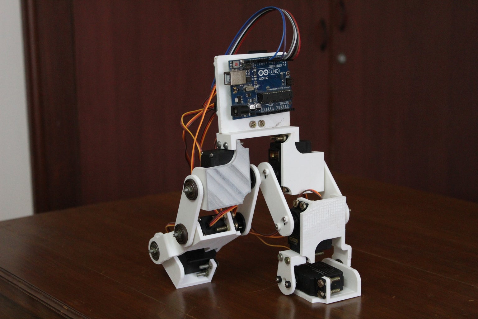
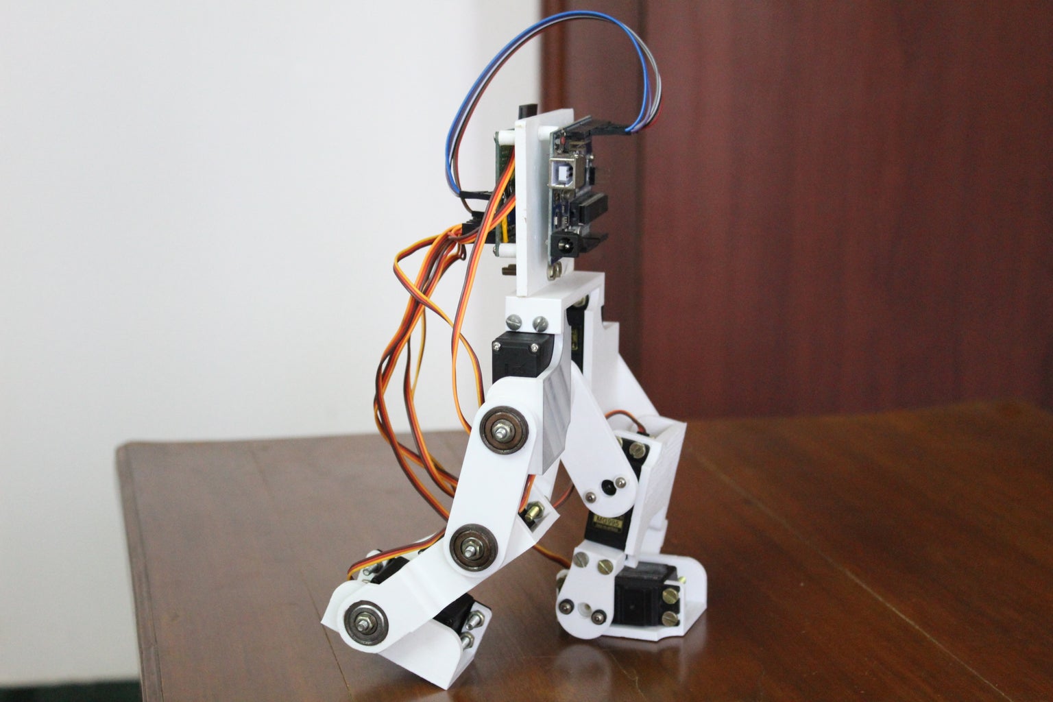
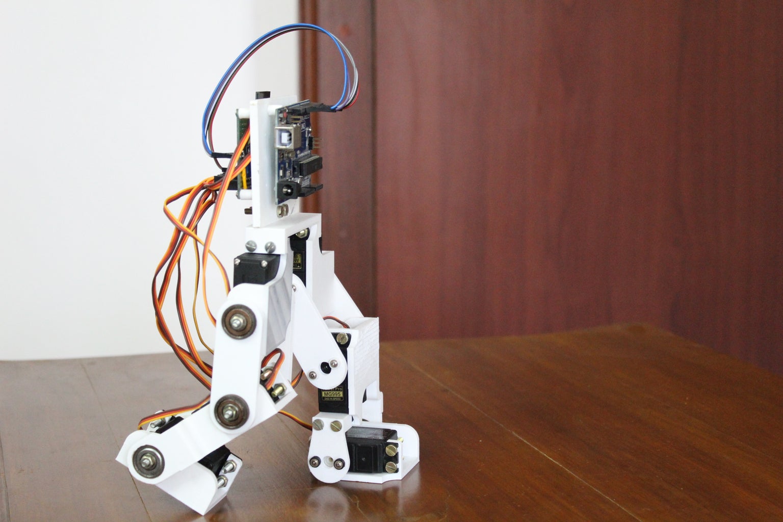
Once the two legs and the electronics are assembled, combine them together to build the robot body. Use the bridge piece to link the two legs together. Use the same mounting holes on the hip servo holder and nuts and bolts that hold the servo motor. Finally, connect the electronics mount to the bridge. Line up the holes on the bridge and electronics mount and use M4 nuts and bolts to make the joint.
Refer to the attached images for help. With this, you have completed the hardware build of the robot. Next, let's jump into the software and bring the robot to life.
Step 10: Intial Setup
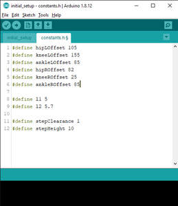
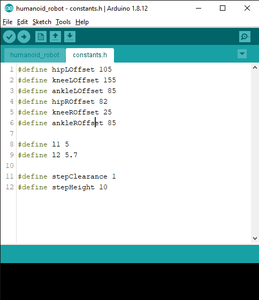
What I've noticed while building this project is that the servo motors and the horns need not align perfectly to stay relatively parallel. This is why the "central position" of each servo motor has to be manually adjusted to align with the legs. To achieve this remove the servo horns from each servo and run the initial_setup.ino sketch. Once the motors have settled in their central position reattach the horns such that the legs are perfectly straight and the foot is perfectly parallel to the ground. If this is the case you are in luck. If not open the constants.h file found on the adjacent tab and modify the servo offset values (lines 1-6) till the legs are perfectly aligned and the foot is flat. Play around with the values and you will get an idea about what is necessary in your case.
Once the constants have been set, note these values as they will be needed later on.
Refer to the pictures for help.
Attachments
Step 11: A Bit About the Kinematics


To make the biped perform useful actions such as running and walking the various gaits need to be programmed in the form of motion paths. Motion paths are paths along which the end effector (the feet in this case) travel along. There are two ways of achieving this:
- One approach would be to feed the joint angles of the various motors in a brute force manner. This approach can be time-consuming, tedious, and also filled with errors since the judgment is purely visual. Instead, there is a smarter way of achieving the desired results.
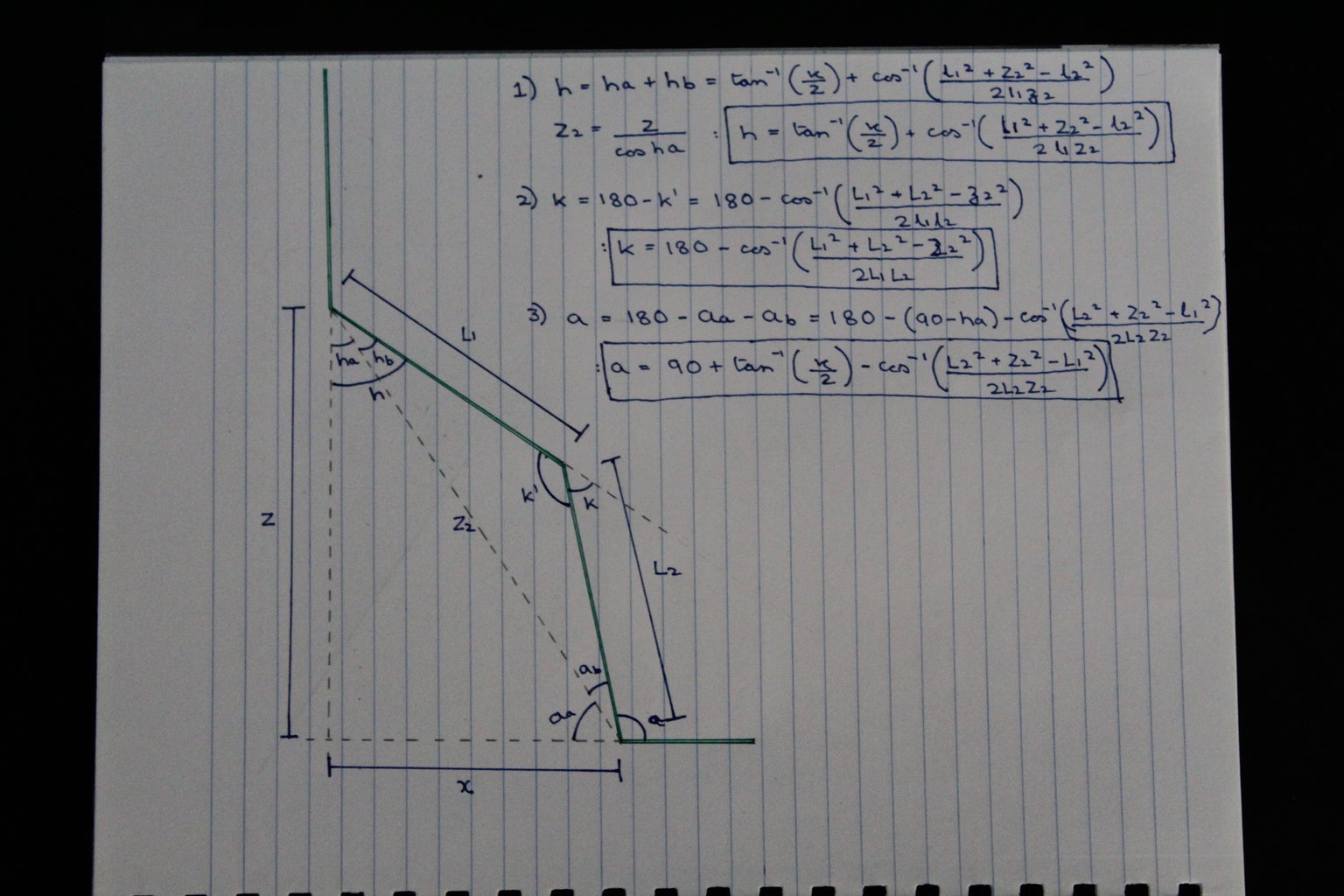
- The second approach revolves around feeding the coordinates of the end effector instead of all the joint angles. This is what is known as Inverse Kinematics. The user inputs coordinates and the joint angles adjust to position the end effector at the specified coordinates. This method can be considered as a black box that takes as inputs a coordinate and outputs the joint angles. For those who are interested in how the trigonometric equations of this black box were developed can look at the diagram above. For those who are not interested, the equations are already programmed and can be used using the pos function which takes as input x, z and outputs three angles corresponding to the motors.
The program containing these functions can be found on the next step.
Step 12: Programming the Arduino

Before programming the Arduino, slight modifications need to be made to the file. Remember the constants I had asked you to take a note off? Modify the same constants to the values you set in the constants.h file.
Note: If you have used the designs provided in this Instructable, you have nothing to change. In case there are some of you who have made their own designs you will have to change a few more values along with the offsets. The constant l1 measures the distance between the hip pivot and knee pivot. The constant l2 measures the distance between the knee pivot and ankle pivot. So if you designed your own model, measure these lengths, and modify the constants. The final two constants are used fo the gaits. The stepClearance constant measures how high the foot will lift while coming forward after a step and the stepHeight constant measures the height from the ground to the hip while its taking steps.
Once all the constants are modified according to your need, you can upload the main program. The main program simply initializes the robot into a walking stance and starts taking steps forward. The functions can be modified according to your need to explore the various gaits, speeds and step lengths to see what works best.
Attachments
Step 13: Final Results: Time to Experiment


The biped can take steps that vary from 10 to 2 cms long without tipping over. The speed too can be varied while keeping the gait balanced. This biped combined with the power of the Arduino provides a robust platform to experiment with various other gaits and other objectives such as jumping or balancing while kicking a ball. I would recommend you to try to change the motion paths of the legs to create your own gaits and discover how various gaits affects the performance of the robot. Sensors such as an IMU and distance sensor can be added to the system to increase its functionalities while force sensors can be added to the legs to experiment with dynamic locomotion on uneven surfaces.
Hope you enjoyed this Instructable and is enough of an inspiration to build your own. If you liked the project do support it by dropping a vote in the "Arduino Contest".
Happy Making!

First Prize in the
Arduino Contest 2020


