

Introduction: Fiber Optic and LEDs - a Wall Decoration


I'm sure many of you saw decorative fiber optic lamps appear a few years ago. I think it was the first widespread use of optical cables for decoration. This was mainly due to the fact that these fibers began to be produced from a material that was much cheaper and easier to handle than glass: plastic. And not just any plastic, but a very transparent one from the PPMA (acrylic) plastics family. Fibers made of this plastic are not brittle, are very easy to bend and they are cheap.
Then there were more and more uses of these fibers: decorative lighting of pools, gardens, houses, there are thousands of projects on the Internet about star ceilings or floors illuminated with fiber optics, fiber optic wearables, fiber optic fabric and many others. These projects uses the so-called end glow fibers, which conducts light from one end of the optical fiber to the other end with as little loss as possible. There are also the so-called side glow fibers that allows light to pass through the optical fiber. They appear in projects such as: decorative lighting of car curbs, furniture, architectural elements, performance halls, just to name a few.
I found a lot of information about the different types of optical cable in this article on instructables, I invite you to read it if you want to know more about plastic decorative optical cables.
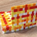
In my project I used 3mm side glow optical fiber, these fibers have WS2812 programmable LEDs attached to the ends, and these LEDs are driven by an Arduino Nano. I mounted the pieces of fiber optics in some frames printed on a 3D printer which I mounted on an MDF board. It turned out, in my opinion, an easy to make, cheap, beautiful and very interesting decoration.
The resemblance to these projects:
is not accidental, I was inspired by them but I wanted to make a much simpler, much easier and much cheaper project.
Step 1: Materials, Components


- PMMA side glow fiber optic cable 3mm thickness approximately 20m;
- 216 WS2812 LEDS, from a 60led/m self-adhesive LED strip;
- Arduino Nano microcontroller;
- 5V/8A power supply;
- 5.5mm DC jack with cable;
- 3D printed parts: body, cover, fixing parts, supports, fiber optic cutting template, Arduino Nano enclosure (based on this enclosure);
- MDF board, natural color, 800mmx800mm with 6mm thickness;
- Some M4 screws (I had a bunch with 50mm length), M4 nuts and washers;
- Wires with different colors for connections;
Fiber optics can be quite expensive if you buy them locally, I spent about $130 on 20 meters, if I had ordered from China (and if I had waited for delivery for at least a month) I would have spent much less.
From the strip of LEDs I cut pieces of three LEDs/piece, and I used 8 pieces in each module, so a total of 9 modules 3 * 8 * 9 = 216. You can see this also in the electronic diagram at the next step.
You can find the components to be 3D printed on Tinkercad.
I ordered the MDF board online, I also gave them a template in svg format to make the holes for fixing the modules and support elements, I attached this template below.
Attachments

Step 2: Schematics

Ultra simple schematics!
Step 3: Construction


The nine modules that make up the decoration consist of nine bodies in which the LEDs are mounted and some parts with which I fixed the modules to the MDF board. So I started the construction with the printing of the module bodies.
Because I used a layer height of 0.3 mm when printing and because I used PLA (which tightens a little when cooled), the 3mm holes in the body where the ends of the fiber optic pieces are inserted must be widened very little, I did this operation manually with a 3mm drill.
Then I made the soldering of 24 LEDs (8 groups of 3 LEDs each). I removed the protective foil behind a group of 3 LEDs and, using the body guidelines, I adjusted the LEDs as precisely as possible next to the 3 mm in holes.
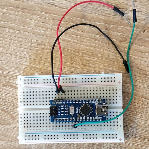
I started this operation near the hole where the connection wires enter and I ended up in the same place, Data IN ( DI ) from the LED strip is the green wire, Data OUT ( DO ) is the blue wire, and the red and black wires are 5V plus respectively Ground exactly as in the photos above. It is good to check before mounting/fixing the LEDs (with a test program) if they all work alright (I have encountered defective LEDs but also LEDs where a color LED or even two do not work).
Below is the test code I used.
#define FASTLED_INTERRUPT_RETRY_COUNT 0
#include "FastLED.h"
#define LED_TYPE    WS2812B
#define DATA_PIN    3
#define COLOR_ORDER GRB
#define NUM_LEDS    24
#define BRIGHTNESS  160
CRGB leds[NUM_LEDS];
void setup() {
	delay(1000);
	Serial.begin(115200);
	LEDS.addLeds<LED_TYPE, DATA_PIN, COLOR_ORDER>(leds, NUM_LEDS).setCorrection(TypicalSMD5050);
	LEDS.setBrightness(BRIGHTNESS);
	Serial.println("FastLed Setup done");
	fill_solid( leds, NUM_LEDS, CRGB(0,0,0));
}
void loop() {
	for( int i = 0 ; i < NUM_LEDS; i++) {
		leds[i] = CRGB(200, 200, 200);
		FastLED.show();
		delay(300);
		leds[i] = CRGB(0,0,0);
		FastLED.show();
		delay(50);
	}
}
If one or more LEDs are not lit up at all or are not lit up white there is a problem with that LED or LEDs For the tests I used an Arduino Nano module mounted on a breadboard as in the photo.
After testing the LEDs the next step is to install the pieces of fiber optics in the bodies. I chose (as you can see in the photos) to join the groups of three LEDs on the left on one side, right on the opposite side and vice versa with pieces of fiber optics with different lengths. Thus the fibers intersect randomly and look quite good. I cut the fibers with a template and a good quality cutter, because it is necessary to make the cuts straight, perpendicular to the length of the fiber. So the ends of the fibers (when inserted through the 3mm holes of the module body) are placed very close to the surface of the LEDs. In this way the transmission of the light from the LEDs to the fiber is done with small losses. It is not necessary to glue the fibers in the body, the 3mm holes do not allow the easy exit of the fiber from its place, so even through this the construction is simple.
While I finished with the nine modules I printed the MDF board support parts and the module fixing parts. I attached the support pieces them to the MDF board. The 50mm screws were too long so I cut them with a universal mini cutter ( dremel like tool ) to a length of about 20mm. Next, I painted the board, I used white acrylic paint.
After the paint has dried, I mounted, with the help of fixing parts, the nine modules on the MDF board. I hot glued the Arduino Nano module with the connection wires (placed in the 3D printed enclosure), on the back of the board and made the rest of the connections according to the electronic scheme, of course, also the 5V power connections. In order for the connections to be more "organized", I used some wire clips, you can fasten them with screws to the mdf board, I glued them to the board with hot glue.
If you want you can do this mounting on a new placed drywall, hiding everything behind it.
Upload the desired program to the Arduino Nano module (in the next step I will present several program variants to choose from), try if everything works correctly and put the covers on.
I chose the place where I will hang my decor and I hung the installation on a screw firmly fixed into the wall.
Done!
Step 4: Software
This wall decoration does not look like any standard application in which LED strips are used. But even so, trying different simple examples and demos of the FastLED library, almost all look very good. Such demos, I have taken from the FastLED's github examples and from Andrew Tuline FastLED-Demos github page but of course I have adapted for the decoration. The ones I personally liked the most can be found below in the video.
The adaptation of the programs consists only in changing the initialization of the LED array ie the total number of LEDs, the type of LEDs, the control pins and the initialization of the LED strip, something like:
//...
//#define DATA_PIN    11
//#define CLK_PIN     13
//#define LED_TYPE    APA102
#define LED_TYPE    WS2811
#define COLOR_ORDER BGR
#define NUM_LEDS    216
#define BRIGHTNESS  160
//...
struct CRGB leds[NUM_LEDS];
//....
//in the setup() function this
FastLED.addLeds<LED_TYPE, 5>(leds, 0, 72).setCorrection(TypicalSMD5050);
FastLED.addLeds<LED_TYPE, 4>(leds, 72, 144).setCorrection(TypicalSMD5050);
FastLED.addLeds<LED_TYPE, 3>(leds, 144, 216).setCorrection(TypicalSMD5050);
You can easily adapt other examples.
Loading them into the Arduino Nano module is particularly easy, there are a lot of examples here on instructables and on the net so I won't insist on it.
It is preferable not to exceed the value of brightness of 160 (as in the code above). The 216 LEDs at maximum intensity and white color can consume approximately 216 * 0.06 = 12.96 A so the 8A power supply will not be enough. At 160 intensity the current consumed would be approximately 216 * 0.06 * (160/255) = 8.13A. Considering that the animations I used never turn on all the LEDs at maximum intensity, the 5V/8A power supply should provide enough power. I had no problems with overconsumption... In addition in some examples FastLED's "setMaxPowerInVoltsAndMilliamps" function is used. Because the number of LED's (216) is changed and is quite high you must change also the volts and milliamps values to something like:
#define VOLTS           5
#define MAX_MA       7000
//...in setup() function
FastLED.setMaxPowerInVoltsAndMilliamps( VOLTS, MAX_MA);
Enough with the words! Below you can follow the examples in action!
The *.ino files that I uploaded to the Arduino Nano for the the corresponding effects from the video.

Step 5: Alternative Constructions
I don't even know where to start because there were so many construction and implementation variants I imagined based on this project 🙂.
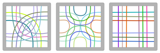
First of all, the fibers can be arranged in a more orderly way as in the graphics below.
Bodies don't have to have a square shape, do they?
They can be hexagonal 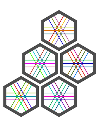
triangular 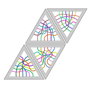
or even some voronoi shapes 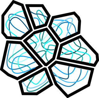
In the case of perpendicular fibers, the fibers can be woven as in a material or the bodies can be redesigned so as to allow the fibers to overlap.
Also here I would mention that I thought about the possibility of using a LEDstrip of 90 LEDs/m and to put in bodies 15 fibers vertically and 15 horizontally so as to make a… WATCH! 🙂 It would be kind of like in the rendering below.

The idea would be that the intersection of the 2 optical fibers lit in red be the hours, green the minutes and blue the seconds. But I'm still in the design phase...
Anyway, you should know that it tempts me (I already have the strip of 90 LEDs/meter 🙂).
A friend saw the modules while I was testing them and told me that even a piece would be beautiful as office décor and my nephew thought that a wall full of these modules and some sound reactive light effects would be great in a modern club or restaurant.
Quite a few options 🙂.
Step 6: A Few Concluding Words
I have to admit that I really like how the project came out. And the people I've shown it so far liked it as well. So I hope that my project will arouse your interest too and I hope that you will find some ideas about how to use these decorative plastic optical fibers in your future projects.
I am waiting for your reactions, your questions and, as far as I can, I will answer them.
I can't wait to see your projects!

Second Prize in the
Plastic Contest


