Design and Modeling of a Parent Big STAR Robot Platform That Carries a Child RSTAR


Department of Mechanical Engineering, Ben Gurion University of the Negev, Beer Sheva 8410501, Israel
*
Author to whom correspondence should be addressed.
Appl. Sci. 2020, 10(24), 8767; https://doi.org/10.3390/app10248767
Submission received: 28 October 2020
/
Revised: 2 December 2020
/
Accepted: 4 December 2020
/
Published: 8 December 2020
(This article belongs to the Section Robotics and Automation)
Abstract
:In this paper we present a wheeled robot platform for child-parent robot collaboration. The new robot, named Big STAR (BSTAR), is fitted with a tail that can act as a ramp to carry and deploy a child RSTAR that can crawl between small cracks and underneath obstacles. Both robots possess sprawling capabilities inspired from insects, enabling them to transform their external geometry and dynamics to overcome a variety of obstacles. The BSTAR can travel at speeds of up to 1.4 m/s, carry payloads of more than five kilograms and travel over rough terrains. The collaboration between the two robots substantially increases their navigability and their capability to overcome obstacles. It increases their working distance and scouting area since the larger robot can act as a charging point for the smaller one. We first describe the design of the newly developed parent BSTAR robot and provide a kinematic and dynamic analysis that determines the force requirements of the robots when collaborating, followed by an evaluation of their mechanical and electrical requirements. We show that under multiple challenging scenarios the robot pair can successfully overcome a variety of obstacles.
1. Introduction
Miniature crawling robots inspired by Nature have long been developed for search and rescue missions that require offroad crawling and climbing over diverse obstacles. Their small size, low weight and high navigability enable their deployment in large numbers to quickly inspect a large area. The many palm sized robots include Mini-Whegs [1], Dyna-RoACH [2], DASH [3], iSprawl [4], OctoRoACH [5], RHex [6], Sprawlita [7], TAYLRoACH [8], STAR [9,10], 1STAR [11] and Rising STAR [12]. At this size, the design of these robots requires a minimalistic approach and reconfigurable mechanics such as sprawling mechanisms, passively transformable wheel-legs, rolling-crawling mechanisms and four bar mechanisms [13,14,15,16,17,18,19,20].
There are several reports of collaboration between robots for offroad tasks such as search and rescue. There are numerous advantages to using multirobot systems which include compensating for a malfunctioning robot, multirobot collaborative control, pioneer and surveyor type robots, multirobot exploration and coverage as well as facilitating wireless communication [21,22,23,24,25]. Khan et al. suggested a framework for a fault tolerant multirobot system that works cooperatively to achieve a common goal [21]. Fong et al. presented a collaborative human robot control for multirobot systems where a single operator simultaneously controls multiple robots [22]. Wagner and Choset developed a framework for multirobot path planning which coordinates robot motion only when needed [23]. Shnaps and Rimon developed a motion planning method for tethered robots to cover an unknown planar environment with obstacles [24]. Min et al. developed a networked robotic system for enhancing wireless communication capabilities which can be used in GPS-denied environments [25].
Vargas et al. considered fitting a large, wheeled robot with a long ramp to carry a smaller tracked robot [26]. They suggested that the robots could be fitted with wireless LAN (local area network) cameras and laser range finders for remote control. However, the combined performance of the robot pair was not presented in typical scenarios and no mechanical properties of the design were provided.
Yang et al. [27] discussed using a large wheeled robot which carries a smaller wheeled robot that can deploy a smaller legged robot. Their main focus was on verifying the communication signal strength between the three robots. Their analysis remained on the conceptual level. Huang et al. analyzed the collaboration between a quadruped hybrid parent robot that can carry up to seven reconfigurable small module robots which can form a chain like a snake [28]. However, similar to the two previous works, they provide no actual demonstration of the system (child-robot) collaboration or any mechanical/kinematic or energy analysis.
In previous publications [9,10,11,12,13], we presented the sprawl tuned family of robots (STAR, 1STAR, RSTAR and FSTAR) which are fitted with a sprawling mechanism inspired by cockroaches [29,30] allowing these robots to transform their dynamics between the lateral to the sagittal planes. The STAR and RSTAR robots exhibited excellent abilities in moving over varying terrains, granular surfaces and when traversing obstacles. The most recent in this series is the flying STAR (FSTAR) which is capable of both driving and flying [31].
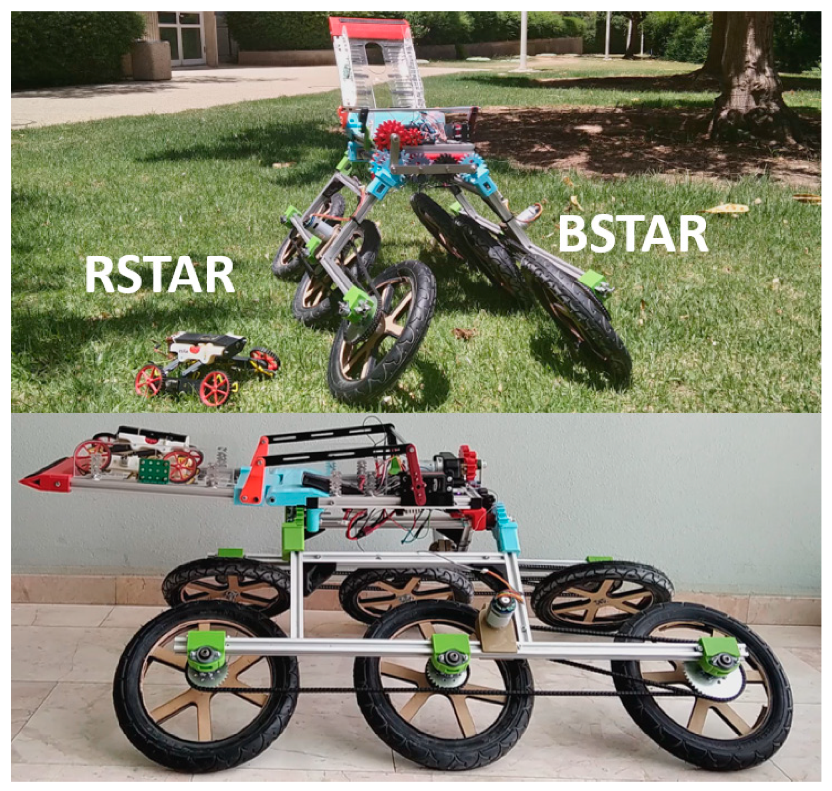
In this work, we present a novel “parent” STAR robot (BSTAR up-scaled by a factor of 7:1 from the original STAR robot and 6:1 relative to RSTAR see Figure 1 and Figure 2) and a previously developed “child” RSTAR robot [12], (see Figure 3). The BSTAR is fitted with an actuated tail enabling the RSTAR to be carried on the back of the BSTAR and easily deployed. This paper is organized as follows. We first present the mechanical design of the two robots and their interface in Section 2. In Section 3 we cover the kinematic and dynamic analysis of the collaboration between the two robots in different scenarios, including their combined working range and scouting areas. In Section 4 we present multiple experiments in which the two robots collaborate to overcome obstacles.
2. Design and Manufacturing
The newly designed BSTAR robot is fitted with a sprawling mechanism similar to the STAR family of robots. Substantial efforts were invested in preserving the simplicity of its design and the low number of motors and actuators.
2.1. Robotic Design
The STAR robots have a rigid body core which holds the controllers, the onboard batteries and the sprawling mechanism which makes it possible to vary the rotation axis of the whegs/wheels as well as their heights and widths. Both sides of the robots are phased together and move symmetrically relative to their centers. Each set of legs is actuated by a single motor. The main specifications of the two robots are presented in Table 1, Figure 2 (BSTAR) and Figure 3 (RSTAR).
2.1.1. The Big STAR (BSTAR—The Parent Robot)
The BSTAR, which is presented for the first time in this manuscript, is a sprawled robot similar to the original lightweight STAR robot [9] and reconfigurable RSTAR [12] but larger than the two by a factor of 7:1 and 6:1 respectively. It is also fitted with a tail to carry, deploy and recover the RSTAR robot. Given the size difference between the new robot and the previous ones, and the fact that it possesses a tail and must be able to carry the smaller robots, it needed to be fully redesigned. Unlike the 3D printed STAR and RSTAR, most of the BSTAR’s body and its transmission must be made of metal to support its larger mass. Further, again due to the size difference, the wheel transmission is now based on roller chains. Attempts to design a lighter version using medium-density fiberboard (MDF) material were unsuccessful.
The BSTAR is designed to carry substantial payloads of batteries, cameras, communication equipment and other sensors for search and rescue missions. The sprawl angle of the Big STAR can be varied in the range of negative 7 degrees to positive 66 degrees. The positive sense of the sprawl angle is downwards and equals zero when the legs are parallel to the body. The BSTAR weighs 9.8 Kg (including batteries and controllers), and its characteristic length (rear wheel axle to front wheel axle) LB is 82.5 cm (5.7 times longer than RSTAR).
The skeleton of the robot, including the main body, two legs and a tail, is made out of 2 × 2 cm aluminum profiles (with a linear density of 3.5 g/cm). The main body, which houses the controller and batteries, is a 22 × 30 cm rectangle constructed of an aluminum profile and Plexiglass.
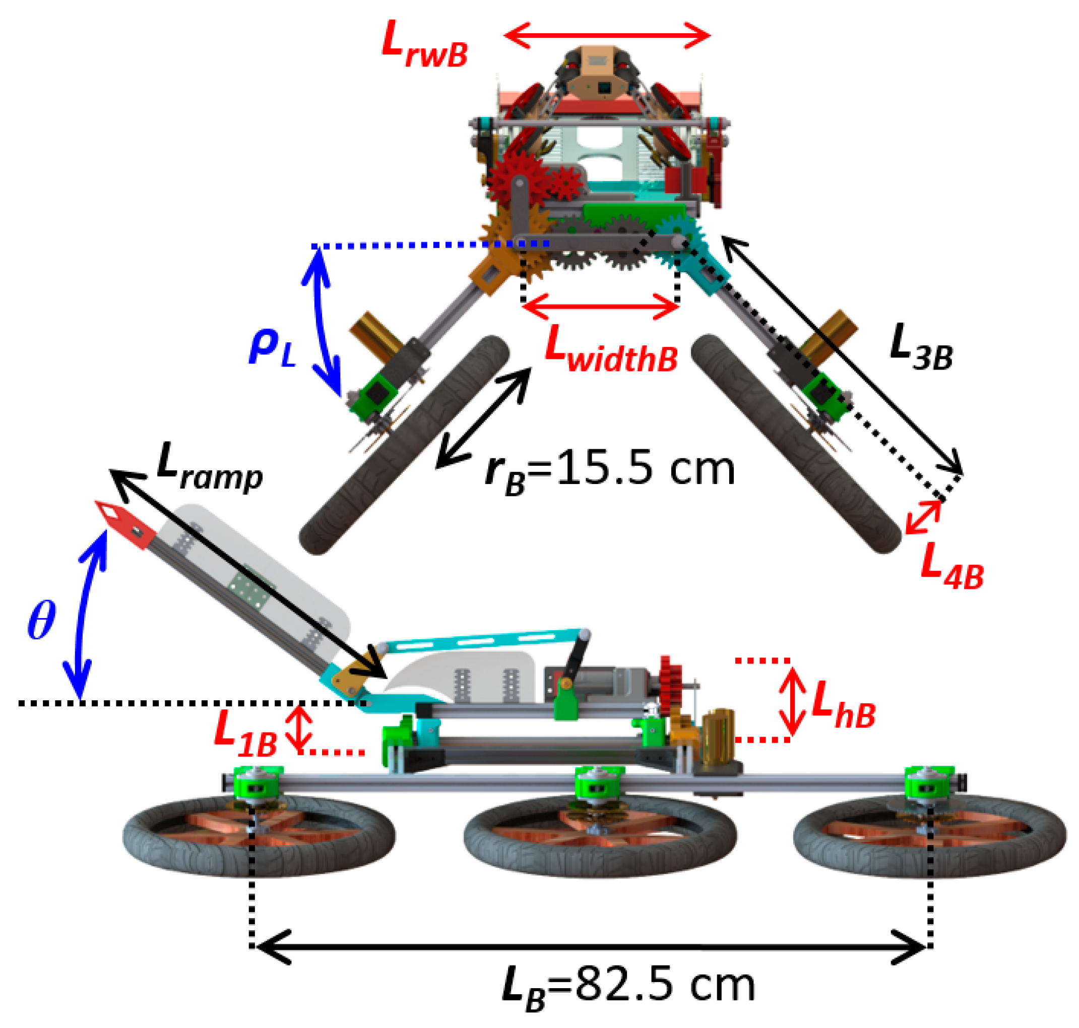
The power transmission of the wheels is based on roller chains and all three wheels on each side are actuated by a single motor. The wheel radius is 15.5 cm. The dimensions of the links of BSTAR are: LB = 82.5 cm, LrwB = 21.1 cm, LwidthB = 5.8 cm, L1B = 5.1 cm, L2B = 2.7 cm, L3B = 42.2 cm, L4B = 6.6 cm, LhB = 9.1 cm and Ltail = 44 cm (see Figure 2).
2.1.2. The Rising STAR (RSTAR—The Child Robot)
The RSTAR, which we recently reported [12] and is presented in Figure 3, is an upgraded version of the STAR [9] fitted with a four bar extension mechanism (FBEM) that allows it to extend the distance between its body and legs and move its center of mass in the fore-aft and vertical directions.
The combination of the sprawling and extension mechanisms enables RSTAR to overcome extremely challenging obstacles, crawl over flexible and slippery surfaces and even climb vertically in a tube or between two walls.
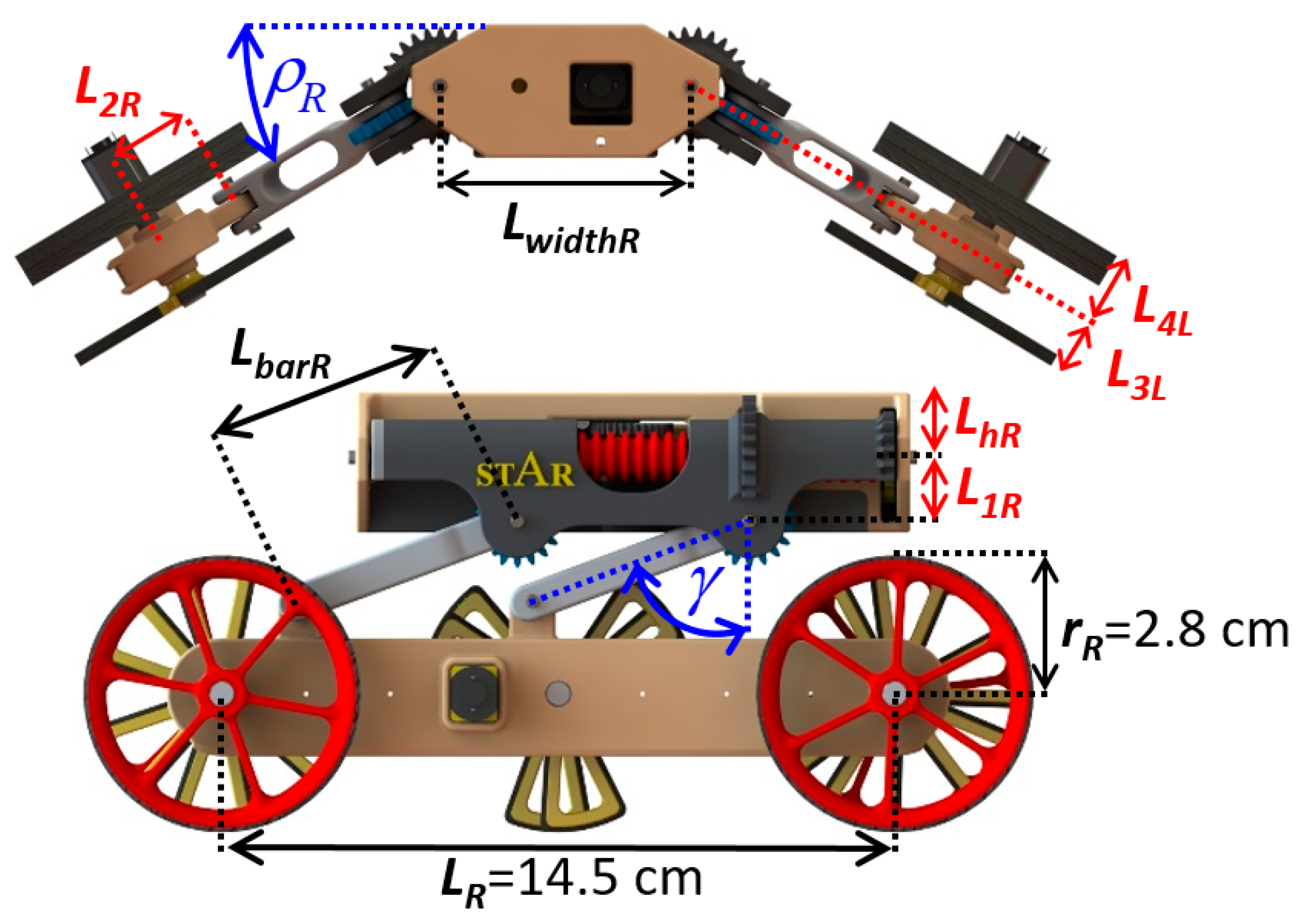
The child robot can extend its height and width by three-fold. Its weight is 380 g and its characteristic length (rear wheel axle to front wheel axle) is 14.5 cm. Further details on the design of RSTAR and a movie featuring its capabilities can be found in our previous work [12]. The dimensions of the links of RSTAR are (see Figure 3): LR = 14.5 cm, Lbar = 5 cm, LhR = 1.4 cm, L1R = 1.4 cm, L2R = 2 cm, LwidthR = 5.7 cm, L3R = 1.3 cm, L4R = 1.6 cm.
2.1.3. The Robots’ Interface
To carry one or multiple RSTAR robots, the BSTAR is fitted with an active tail mounted on its main body. The tail is actuated by a DC motor, which can be lowered to negative 43 degrees to reach ground level (or lower) thus allowing RSTAR to climb on it. The tail can also be raised to positive 55 degrees to deploy the RSTAR on higher surfaces and can reach a maximum height of 88 cm.
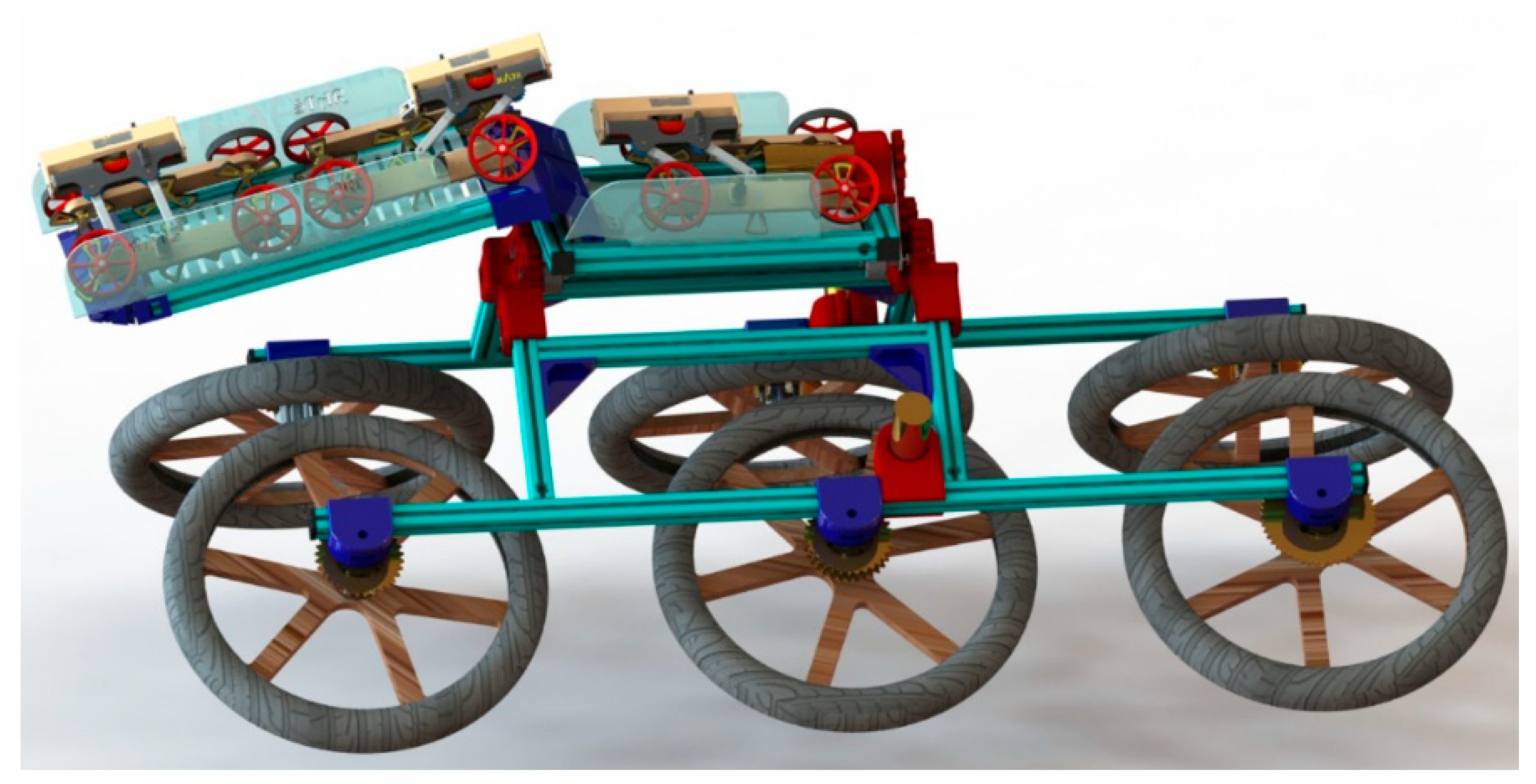
The tail and the main body have Plexiglass walls on each side allowing the RSTAR to apply pressure on the walls to maintain itself firmly while being carried by BSTAR. The BSTAR can carry up to three RSTAR robots, one on its main body and two on the tail (Figure 4). The tail can be fitted with an electric recharging point to recharge the RSTARs using onboard batteries. The docking to the charging point is very simple since the RSTAR only has to be in contact with both walls and raise or lower its main body to magnetically connect with it.
2.2. Actuation and Control
Like the RSTAR, the BSTAR is also actuated by a total of four motors with a built-in gearbox and encoders.
2.2.1. Driving Wheels
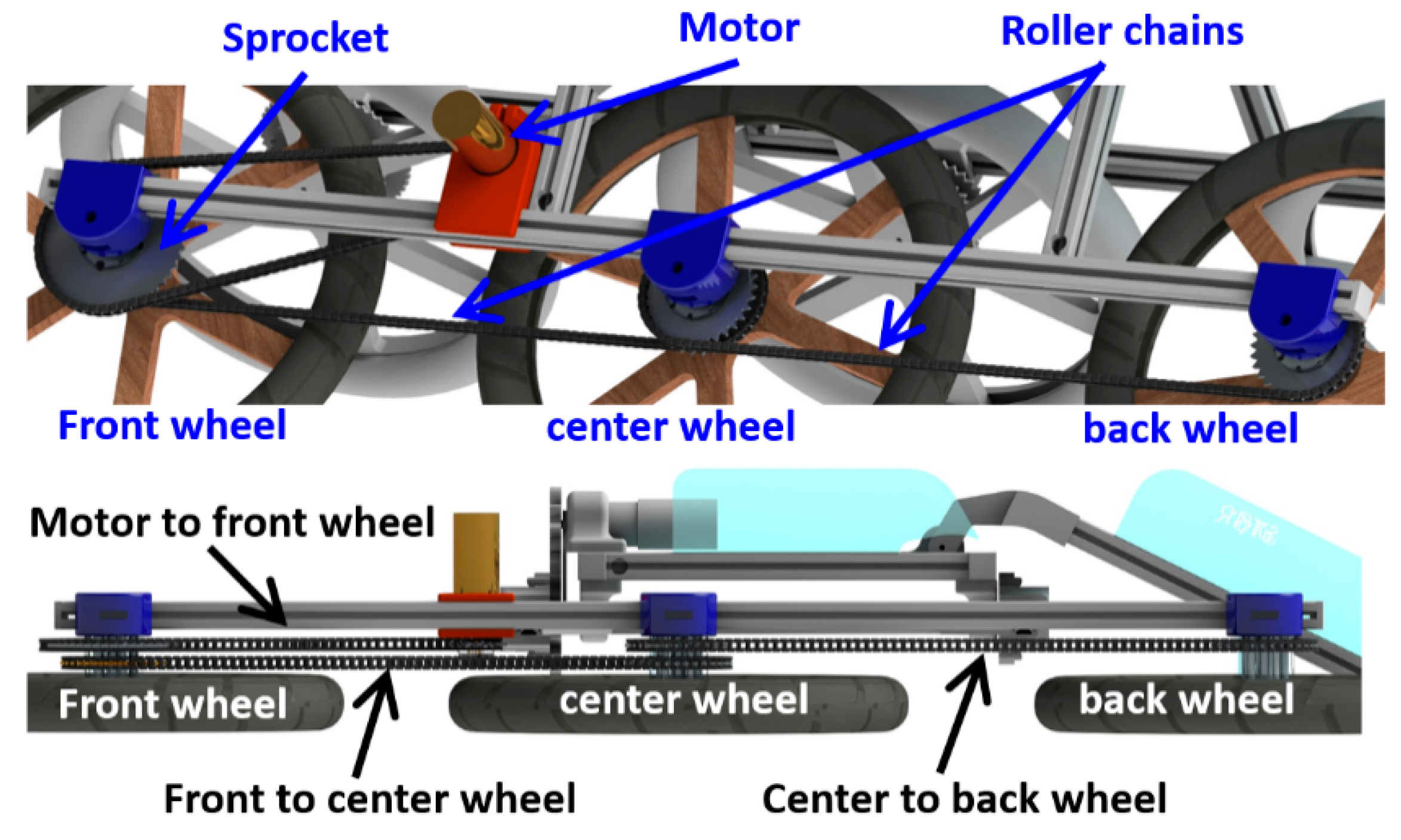
Two motors are used to drive the wheels (one for each set of wheels). These motors provide a torque of 2.94 Nm and a rotational speed of up to 276 RPM. We implemented a gear speed reduction of 3:1 (using sprockets) which increases the torque to 8.83 Nm at 92 RPM thus providing a maximum linear speed of 1.4 m/s. Plastic roller chains are used to transmit the torque from the driving motors to the wheels through aluminum sprockets attached to the motor and wheels (see Figure 5). The first roller chain connects the motor to the front wheel while reducing the speed ratio by 1:3. A second chain connects the front wheels to the center wheel and a third one connects the center wheel to the back wheel. The motor and wheels are attached to the aluminum bars using 3D printed parts which are press fitted and screwed to the profile of the bars.
2.2.2. Sprawl
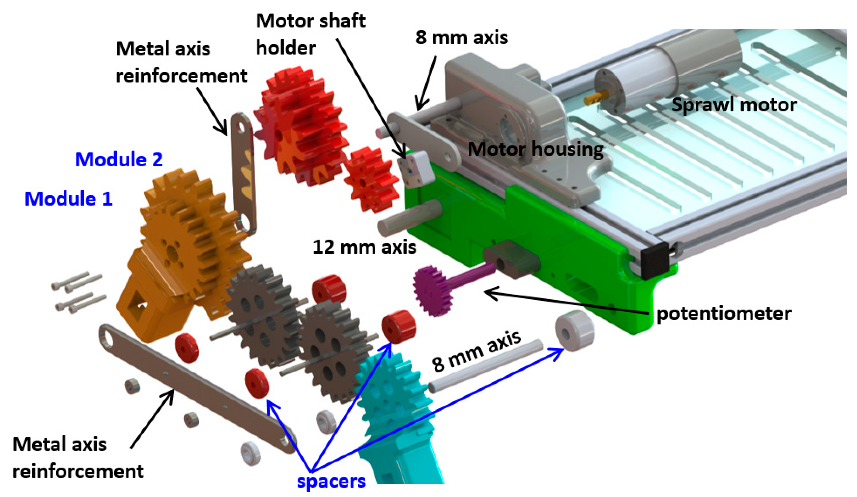
The sprawl is actuated by a 32 mm motor with a gear ratio of 1:2, providing a torque of 114.5 Nm at 36 degrees/second. The 3D printed gears of the robot have a module of 4 mm and a width of 11 mm to ensure that they can hold the maximum load when the sprawl is in raising mode (see Figure 6). A pair of spur gears is used at the back of the robot. The pair of gears at the back is essential to ensure that both sides of the sprawl (front and back) remain adjusted. A 12 mm rod is used to distribute the load between the front and back of the sprawl mechanism. Steel bars prevent the axes of the gears of the sprawl mechanism from separating as a result of the radial forces caused by the load. The angular orientation of the sprawl is measured using a potentiometer connected to the main Arduino controller. More details on the design of the sprawl and the other mechanisms can be found in the Appendix A.
2.2.3. Tail (Ramp)
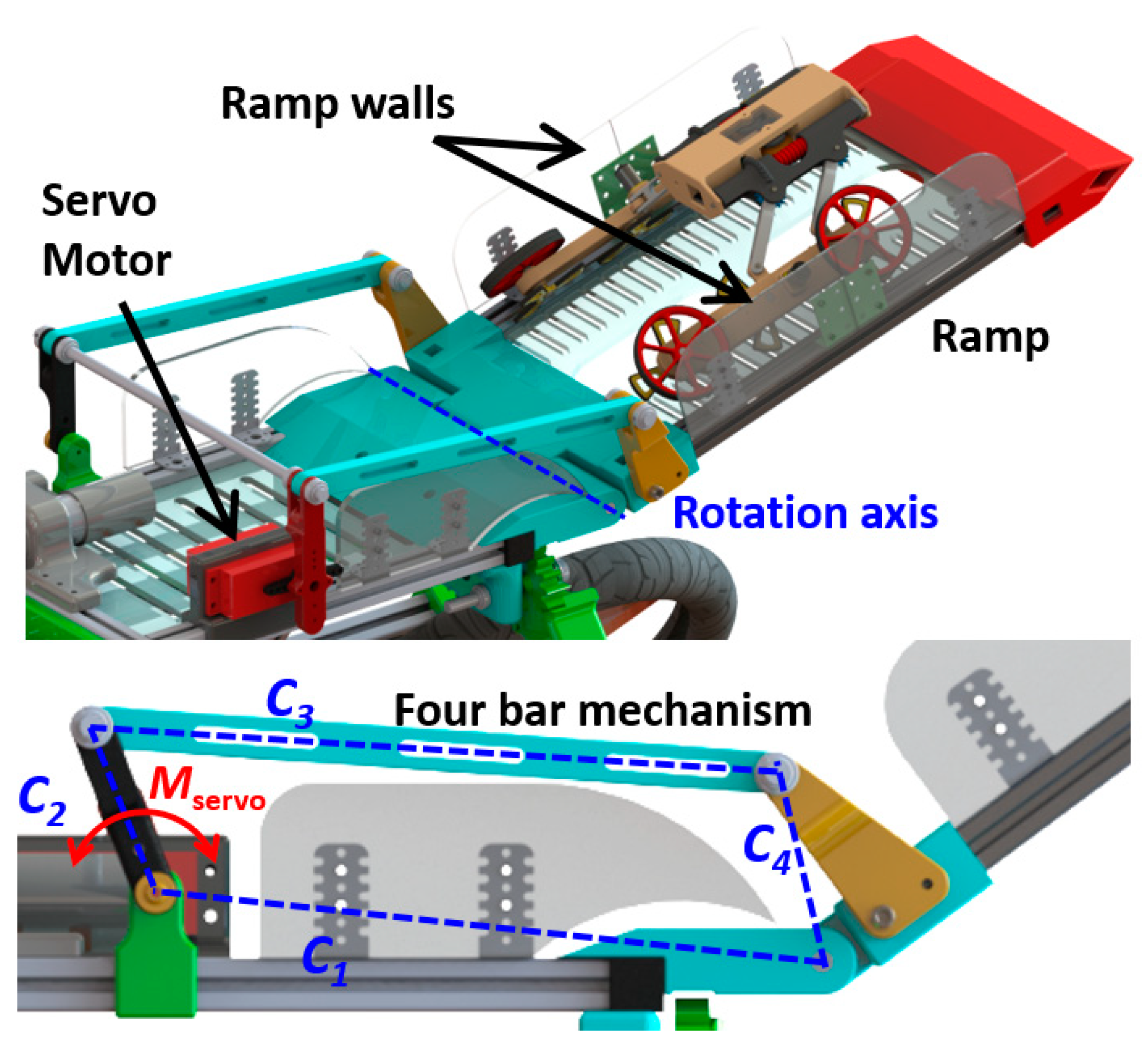
The tail must be able to carry and lift at least one RSTAR (resulting in nearly 3 Nm when it is horizontal) In this design, we used a servo motor which provides a torque of 4.41 Nm (45 kgcm as per the catalog specifications) at 130 degrees/second. The servo motor actuates a four-bar mechanism which was optimized to increase the output torque of the tail. The tail can be lowered to negative 40 degrees or raised to positive 55 degrees (76 degrees in the previous version) to deploy the RSTAR on higher surfaces (up to a maximum height of 88 cm). Climbing this high a slope is possible since RSTAR can extend its width to apply pressure on the walls of the ramp and even climb vertically (see Figure 7).
2.2.4. Microcontroller
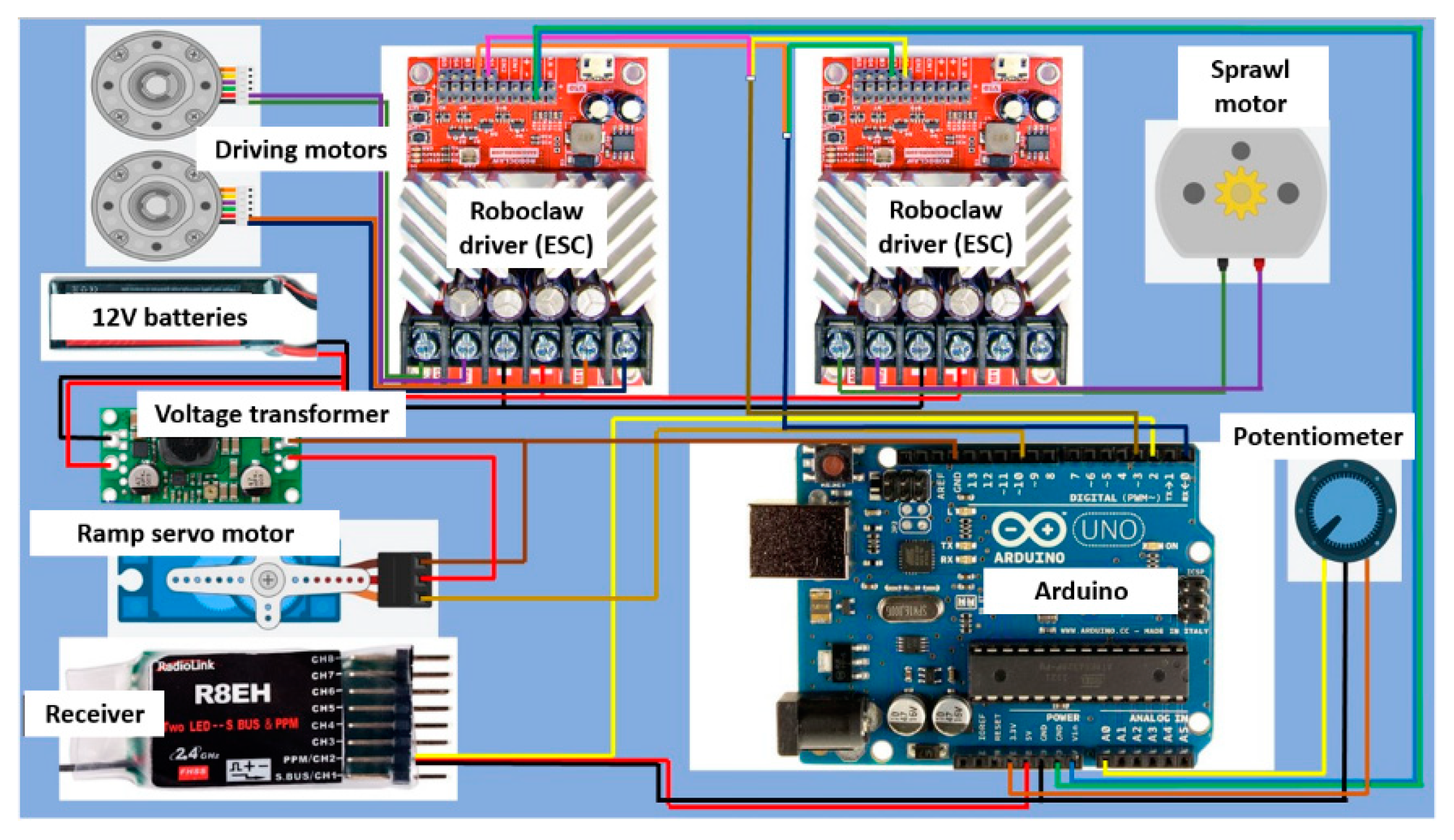
To control the four motors and collect sensor data, we used an Arduino Uno microcontroller board as the main controller and two BASICMICRO RoboClaw drivers which provide a current of up to 15 Amperes. The driving motors, fitted with encorders, are directly attached to the RoboClaw ESC drivers which control their speed based on the Arduino controller’s input. The sprawl of BSTAR is instrumented with a potentiometer which is used to measure the sprawl angle and control its orientation in PID closed-loop using the Arduino controller (see Figure 8). The analog voltage is then transformed to a digital value by the controller. The controller evaluates the error between the actual and the target angle and using the PID controller it controls the sprawl angle with the duty cycle of the motor. The gains are experimentally tuned to minimize the error and overshoot (the normalized gain values are: kp = 1, ki = 0.5, and kd = 0.25). The Arduino is also responsible for controlling the position of the servo motor which actuates the ramp. The BSTAR is powered with two 11.1 Volt 5200 mAh LiPo batteries. The Arduino is connected to a receiver to respond to commands from a human operator but is also preprogrammed to perform basic tasks (motion sequences of the sprawl, ramp and driving motors) to dispatch or recover the RSTAR for example.
2.3. Manufacturing
The child robot’s mechanical parts were mostly manufactured by 3D printing. We used an Objet Connex 350 3D printer whose accuracy is roughly 0.05 mm (material type VeroWhite RGD 835) and Ultimaker 2+ with PLA (0.15 mm accuracy).
The parent robot was manufactured out of aluminum profiles for the skeleton, ABS and PLA 3D printed parts for the gears and the connectors, Medium Density Fiberboard (MDF) boards for the wheels and Perspex (Plexiglas—PMMA) boards for its body, tail floor and housing. Considerable efforts were made to simplify part replacement, which is essential for experimentation in different conditions and in case components are damaged during risky maneuvers
2.4. Design Considerations, Challenges and Scalability
The size of the robots is predetermined by multiple constraints. The size of the RSTAR is defined by its ability to carry sensors, control board cameras, etc. Real life robots of this size typically weigh at least a few hundred grams and their typical length is 10 to 20 cm. Although the BSTAR can be developed at scales ranging from 50 cm to a few meters, we opted for the smallest design that could still operate with good maneuverability while carrying 1–3 RSTAR child robots. Note that our attempts to develop a smaller BSTAR design (dubbed LSTAR) which corresponded to 70% of the scale of the current design, weighed nearly 5 kg and was built out of MDF were unsuccessful because the robot was too small to perform the operations. The MDF material also proved to be too flexible at this scale to carry the motors and battery or maintain the tension of the roller chains.
Because the RSTAR is carried on the back of BSTAR, the size of BSTAR’s main body is defined by the width of RSTAR. The sprawling mechanism of BSTAR makes it possible to substantially shorten the length of the tail compared to other robots. Although the minimum length of the tail needs to be one body length of the RSTAR, we opted for a longer tail (44 cm) which can carry two RSTAR robots. When the tail angle is negative 30 degrees, the BSTAR can boost the RSTAR so it can climb over the edge of a sidewalk, for example.
The choice of battery size and the number of RSTARs carried depends on the specific task the robots are required to perform. For example, carrying more than a single RSTAR will not increase the range of the two robots (one RSTAR and one BSTAR) but can increase the scouting area that multiple robots can cover together.
3. Kinematic and Dynamic Analysis
In this section, we analyze the kinematics and dynamics of both robots. We present the robots’ range of configurations and the characteristics of the obstacles they can overcome separately and cooperatively. In the dynamics’ analysis, we evaluate the torque requirements of the motors and the forces required to keep the RSTAR safely attached to the BSTAR. These results guided the design of the robots and the choice of motors. We use the physical values of the actual robots depicted in Table 1 and Figure 2 and Figure 3.
3.1. Robot Kinematics
3.1.1. Rising STAR
Despite its size, the RSTAR can go over obstacles very efficiently because it can climb over steep obstacles measuring up to 6.5 cm (its wheel diameter is only 5.6 cm) by implementing different planning strategies to actuate the sprawl and FBEM mechanisms. The robot can also climb vertically in a tube or between two walls. The robot’s width and height can be varied by changing the sprawl and the FBEM angles. Denoting the sum of the bars L1R+ L2R+ rR by LxR, the width of the robots is:
Alternatively, the general relationship between the values of the FBEM mechanism γ and the sprawl angle ρR can be expressed as a function of the width of the tail LrwL:
The minimum width of the robot, 8.9 cm, corresponds to a sprawl angle of 90 degrees. Its maximum width, 28.5 cm, is obtained when the sprawl and FBEM angles are both at zero degrees. The RSTAR’s height is:
The minimum height of the RSTAR, 3.5 cm, is obtained when the FBEM angle is at either positive or negative 63 degrees (its range limit) and a sprawl angle of 5 degrees (the minimum sprawl at which RSTAR can still advance).
3.1.2. Big STAR
The BSTAR is capable of climbing over obstacles that are up to 17.5 cm high (depending on the friction between its wheels and the obstacles) and can travel over stones, rubble and other rough surfaces while the RSTAR robot remains tightly secured to its back (see video in Supplementary Materials). The LSAR’s width and height are a function of its sprawl alone. Its width is:
Its minimum width, 32.5 cm, is obtained at a sprawl angle of 66 degrees whereas its maximum width is 118 cm. The robot’s height hB is:
The height of the BSTAR ranges from 21 cm at 7 degrees (the minimum sprawl that still allows the robot to advance), to 66 cm.
3.1.3. The Tail
The tail’s orientation relative to the body θ can be varied in the range of negative 43 degrees to positive 76 degrees. Its height hTail is a function of both the sprawl angle ρB and the tail orientation θ:
For a sprawl of 66 degrees and a tail angle of 76 degrees, the maximum height of the tail is 88 cm (see video in Supplementary Materials). The tail can be lowered to −18 cm (ρB = 0 and θ = −43 degrees) allowing RSTAR to climb on it from a lower surface.
Given that the maximum height that each can reach on its own is 6.5 cm and 17.5 cm, the collaboration of the two robots allows them to increase the height that they can reach by five fold. It can be further increased if a longer ramp is used.
3.2. Force Analysis of RSTAR
The RSTAR is designed to climb vertically between the walls of the tail (or in tubes) by applying pressure to the walls of the tail. First, the wheels must have a sufficient torque for climbing vertically. To rotate the wheels, the torque required by each of the side motors TWR is:
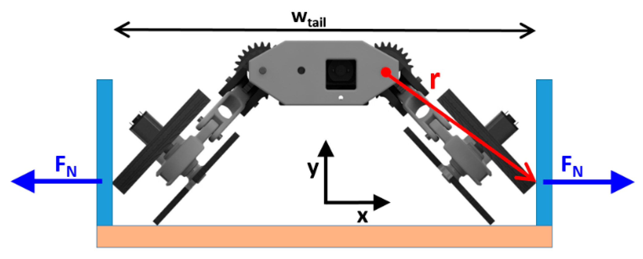
which is equivalent to 0.0532 Nm of torque, not including friction on each motor to climb vertically. The RSTAR must apply a normal force FN to the walls (see Figure 9):
The coefficient of friction (COF) between the RSTAR wheels and the BSTAR tail is μ = 0.8. Because the weight of RSTAR is 380 g, it must apply a minimum normal force of 4.9 N. The torques acting on the sprawl and FBEM joints, respectively Msprawl and MFBEM, can be calculated using:
and
where r is the vector distance from the sprawl joint to the wall:
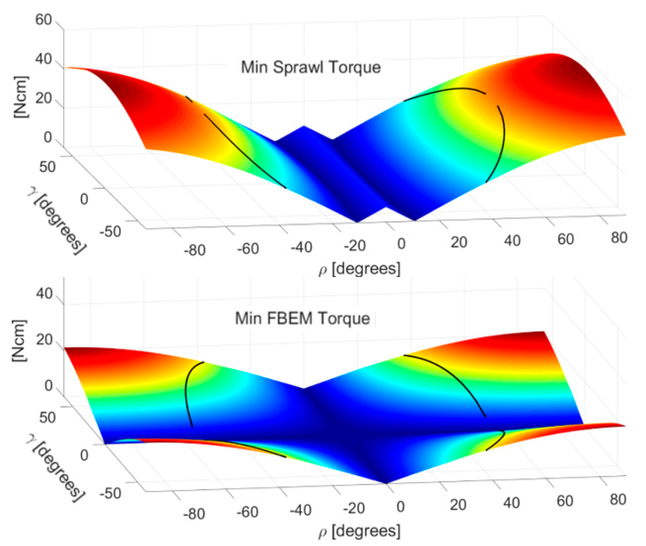
Figure 10 presents the minimum torques as a function of the sprawl ρR and FBEM γ angles that must be applied by the sprawl and FBEM joints to maintain the normal force of 4.9 Newtons to the walls needed to climb vertically. The black lines present the values of ρR and γ when the robot is in contact with walls of the tail (the tail width is 21 cm).
Figure 10 shows that the torque which must be applied by the sprawl is almost twice as large as the torque applied by the FBEM. In order to reduce the torques applied by each of the mechanisms, the width of the ramp (zero sprawl and zero FBEM) should ideally be increased. However, given that the width of the ramp Wtail (the black line in the figure) is restricted by the size of the robot, the best strategy consists of using a maximum FBEM angle (γ = 55 degrees) and a minimum sprawl (ρ = 20 degrees) which results in the smallest torques for both joints (nearly 0.20 Nm).
3.3. Navigability
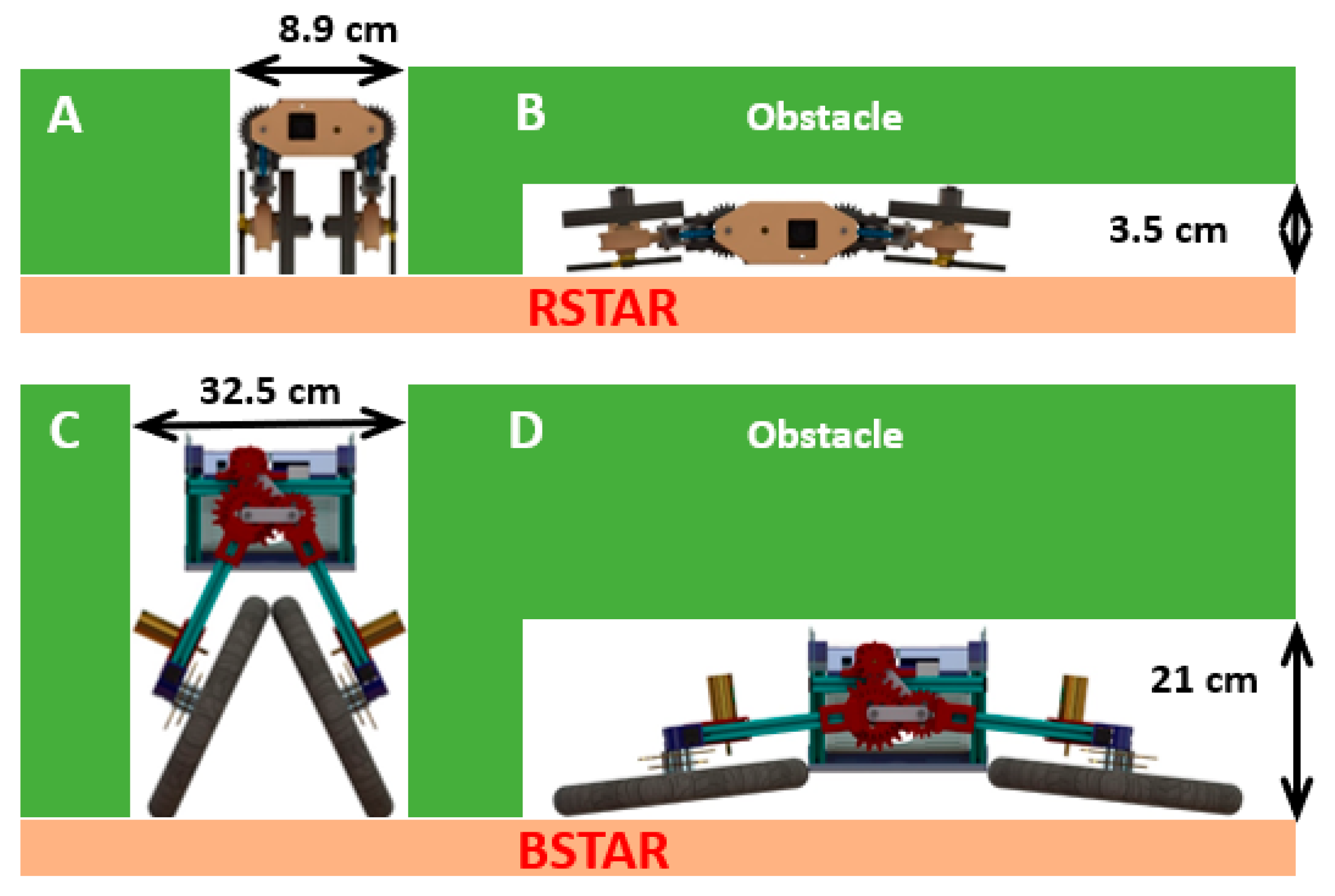
The sprawl mechanism allows the STAR robots to change their width and height to sneak between obstacles. The RSTAR can crawl underneath an obstacle that is 3.5 cm high and reduce its width to go between obstacles that are 8.9 cm apart. The BSTAR can crawl under obstacles 21 cm high and between obstacles 32.5 cm apart (see Figure 11).
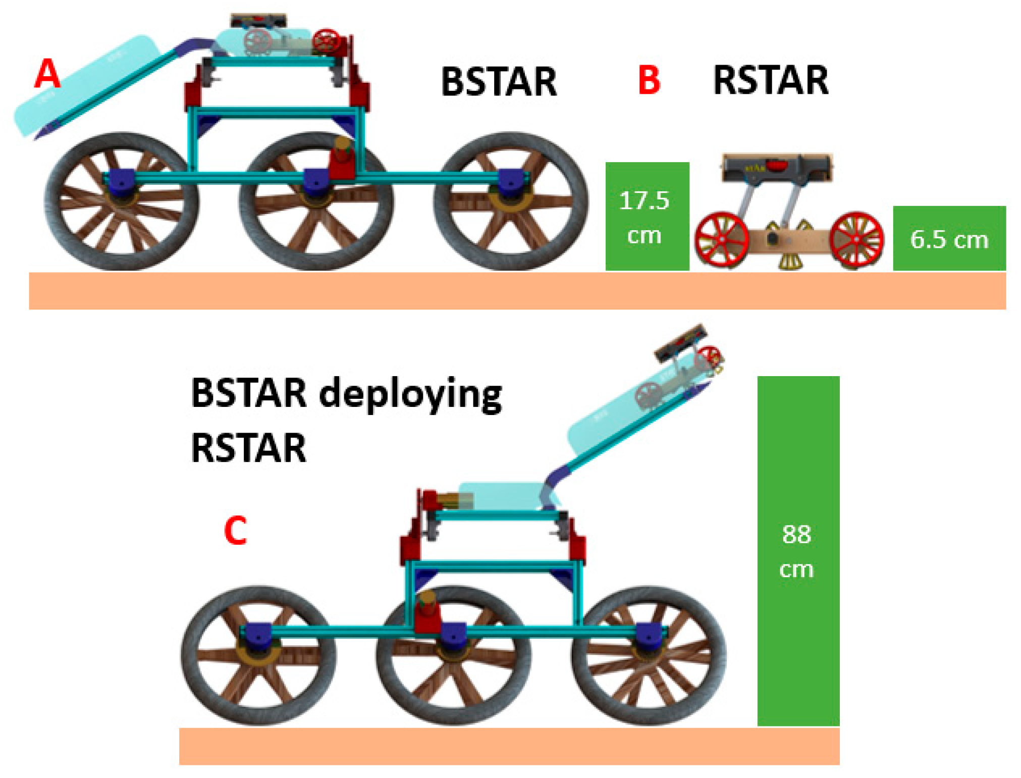
The BSTAR can climb on top of obstacles that are 17.5 cm high, which is slightly more than its wheel radius, and the RSTAR can climb over obstacles that are 6.5 cm high (see Figure 12).
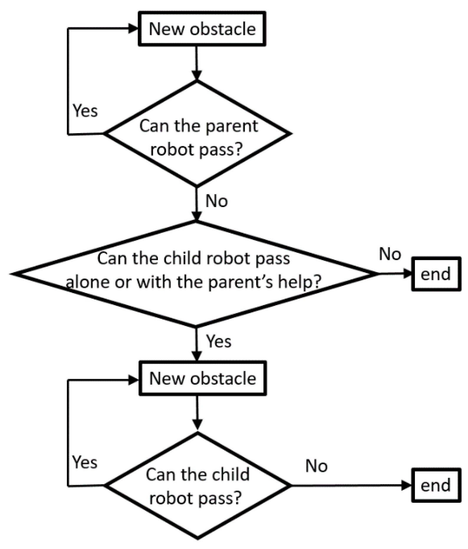
Since the parent robot carries the child robot, the RSTAR can go anywhere the BSTAR can go (the opposite is not true). Therefore, the BSTAR can deploy the RSTAR which can then continue alone. Figure 13 presents a flowchart of the order of obstacles that the collaborating robots can overcome.
3.4. Working Range
The Cost of Transport (COT or specific resistance) is defined as the power consumption divided by the weight multiplied by the speed of the robot or as the energy required to travel a distance divided by the weight times the distance.
where m is the mass of the robot, g is the gravity, E is the consumed energy for the travelled distance d and v is the speed. Given that RSTAR consumes 3.33 Watts at 0.8 m/s [12] and that the power consumption of BSTAR at 1.43 m/s is 50.62 Watts (see Section 4.3.1), the COT of RSTAR and BSTAR are respectively 1.12 and 0.37.
3.4.1. Maximum Working Range
Using Equation (12), the total distance d that can be travelled using the robot’s onboard batteries can be calculated:
For the given masses of the robots and their battery sizes (see Table 1), the maximum ranges of the RSTAR and BSTAR are respectively 5.12 km and 11.7 km. The combined range of both robots, in the case where BSTAR is carrying RSTAR and then deploying it, is almost 17 km.
3.4.2. BSTAR as a Charging Point for Scanning Operations
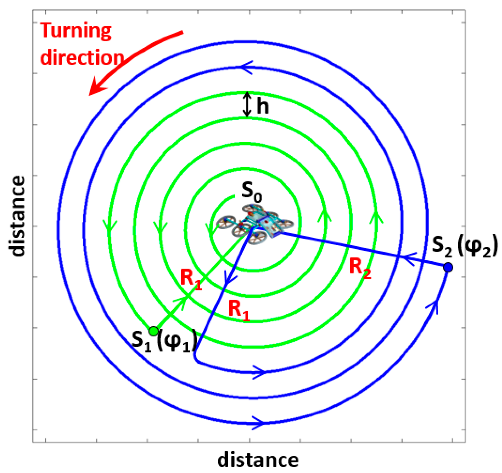
If the robots’ mission is to scan/scout a specific area, the scanning area can be substantially increased if the BSTAR, which can carry up to three RSTARs, acts as a mobile charger for the smaller robots. Using BSTAR’s battery (which can charge an RSTAR’s battery 20 times), the RSTAR robots can travel a total cumulative distance of 105 km. Assuming that scouting takes place in an open area implementing a spiral path and the scanning range is 2 m on either side (the distance between two lines of the spiral is h = 4 m), the area the robots can scan, assuming that the BSTAR is at the center of the spiral, can be calculated.
The length of the spiral, from point Si to point Si+1 is:
where LSi is the spiral length between points Si(φi) and Si+1(φi+1), h is the distance between two consecutive spiral lines (h = 4 m in our example) and φi is the angular position of point i (see Figure 14). Starting from S0, the RSTAR travels a distance LS0 to point S1 and returns a radial distance R1 to S0 to recharge its battery on BSTAR. In the second run after recharging, the robot travels back a distance of R1 to S1, rotates a distance LS1 along the spiral and returns a radial distance R2 back to BSTAR). The length of the radius Ri is:
The maximum distance the RSTAR can travel without recharging dR is equal to the sum of the distance travelled along the spiral plus the radial distance back and forth:
Given that the range of the RSTAR dR and the location of the previous stop Si(φi+1) are known, Equation (16) must be numerically solved to calculate the location of the next stop Si+1(φi+1). Since the RSTAR can be recharged 20 times using the BSTAR battery, the total area that can be explored is 0.375 km2. Note that as the area and the radii increase, some of the travelling distance is lost on the return trip to the previous stop and back to the charging base. The ratio of the scanned distance to the total distance travelled is 90.6%, 86.7% and 81.4% respectively for 10, 20 and 40 recharging times.
3.4.3. Reducing Exploration Time
Using multiple child robots can reduce the exploration time of an area substantially. Assuming that the BSTAR is carrying N (one to three) RSTAR robots which are simultaneously exploring an area, the area exploration rate AER (area scanned per time) is:
The exploration rate of all robots simultaneously exploring (without recharging) is 15.3 m2/s and the total area that can be explored is 0.108 km2. If BSTAR is acting as the charging point for the RSTAR robots, the exploration rate becomes a function of the charging time Tcharging and the working time Tduty of the child robots:
If the RSTAR robots are working alone (without the BSTAR) but continuously recharging their batteries from the BSTAR (TdutyR = 1.77 h and TchargingR = 1 h), the AER is 6.1 m2/s and the total explored area is 0.375 km2.
This methodology makes it possible to determine the size of battery that the parent robot can carry and the maximum effective distance that the robots can scout together as a function of the range of the RSTAR. For example, beyond 40 recharging cycles, it would be more advantageous to increase the battery size of the child robot to increase the efficiency of the scouting by reducing the time and distance that the child robots spend travelling back and forth from the parent robot to the scouting target zone.
4. Results
This section presents the results of experiments conducted on the two robots. We measured their energy consumption and tested the capabilities of the BSTAR when travelling over different surfaces, and carrying, dispatching and recovering the RSTAR robot (see video in Supplementary Materials). During the experiments, the robots were controlled by a human operator.
4.1. The BSTAR
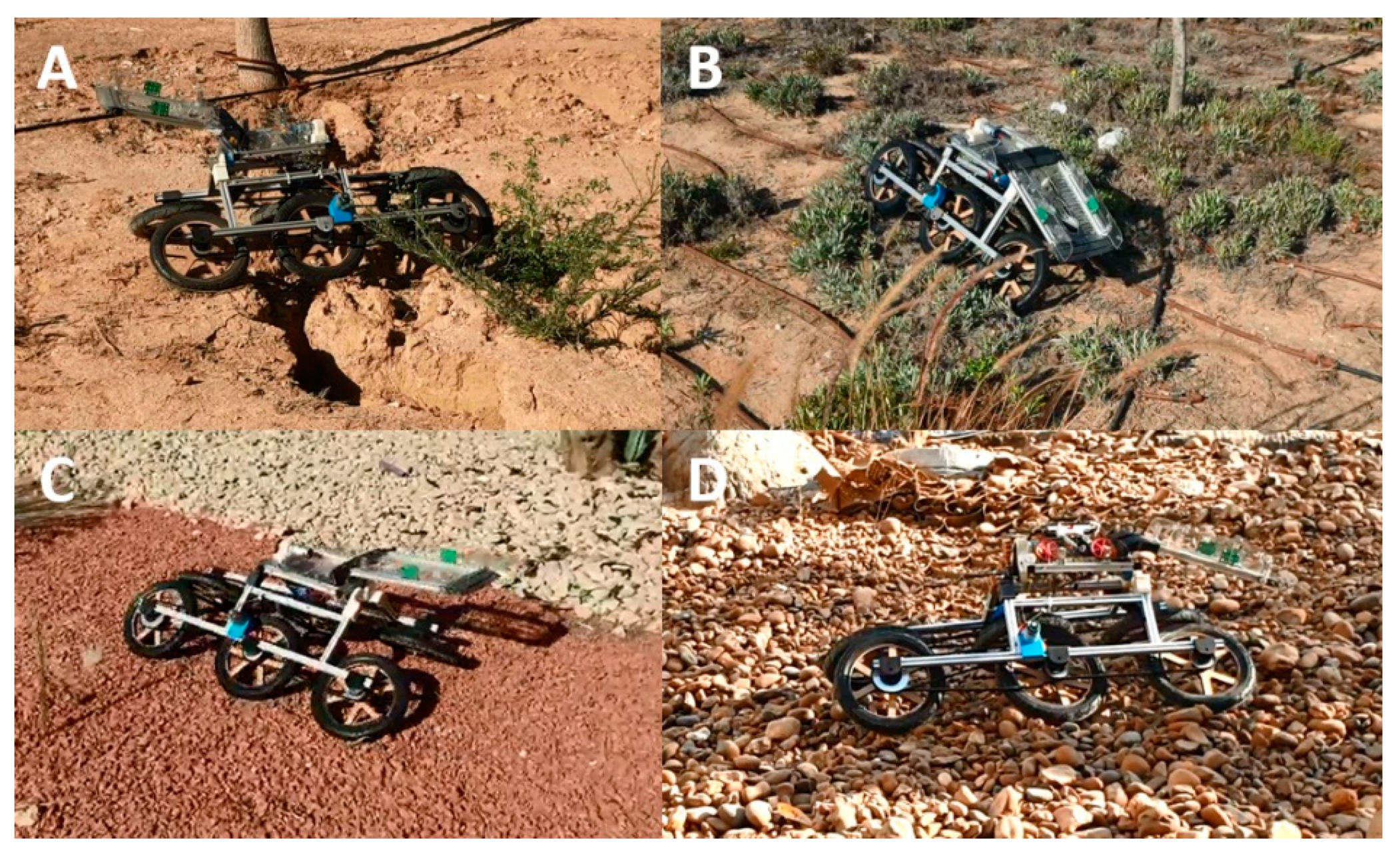
The newly developed BSTAR was tested while travelling over different terrains, including granular surfaces and rocky areas. It can easily travel over cracks in the surface while carrying the RSTAR. Figure 15 illustrates some of the different surfaces the robot can cross (see video in Supplementary Materials).
4.2. Deploying and Recovering RSTAR
4.2.1. Remote Control Operation
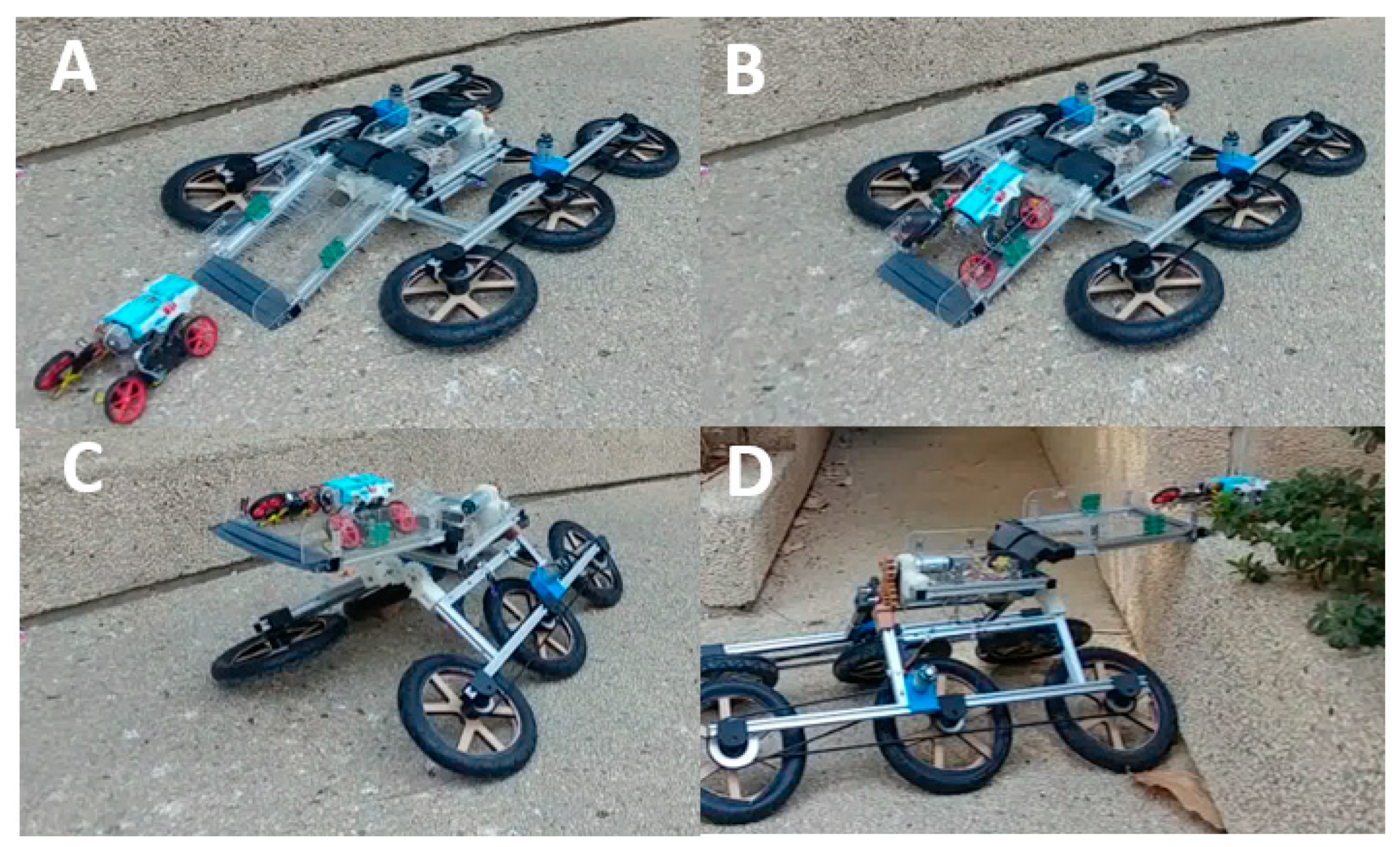
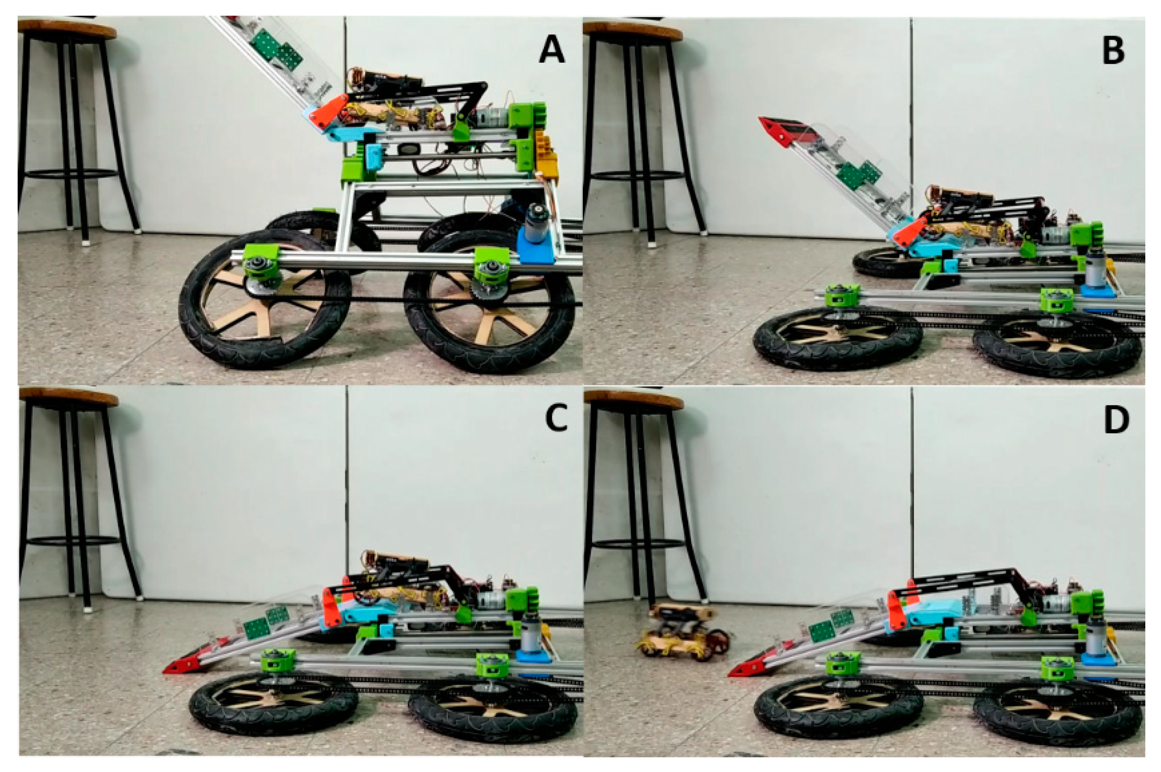
In Figure 16A, the RSTAR is in the vicinity of the BSTAR. At this point, the BSTAR is controlled (radio control) to lower its body and tail (B) and RSTAR drives to climb on the tail (C). Finally, the BSTAR raises its body back to continue driving and deploying RSTAR over a fence that is 42 cm high (D). In another experiment, the RSTAR was deployed at a height of 72 cm (see attached video).
4.2.2. Automatic Features
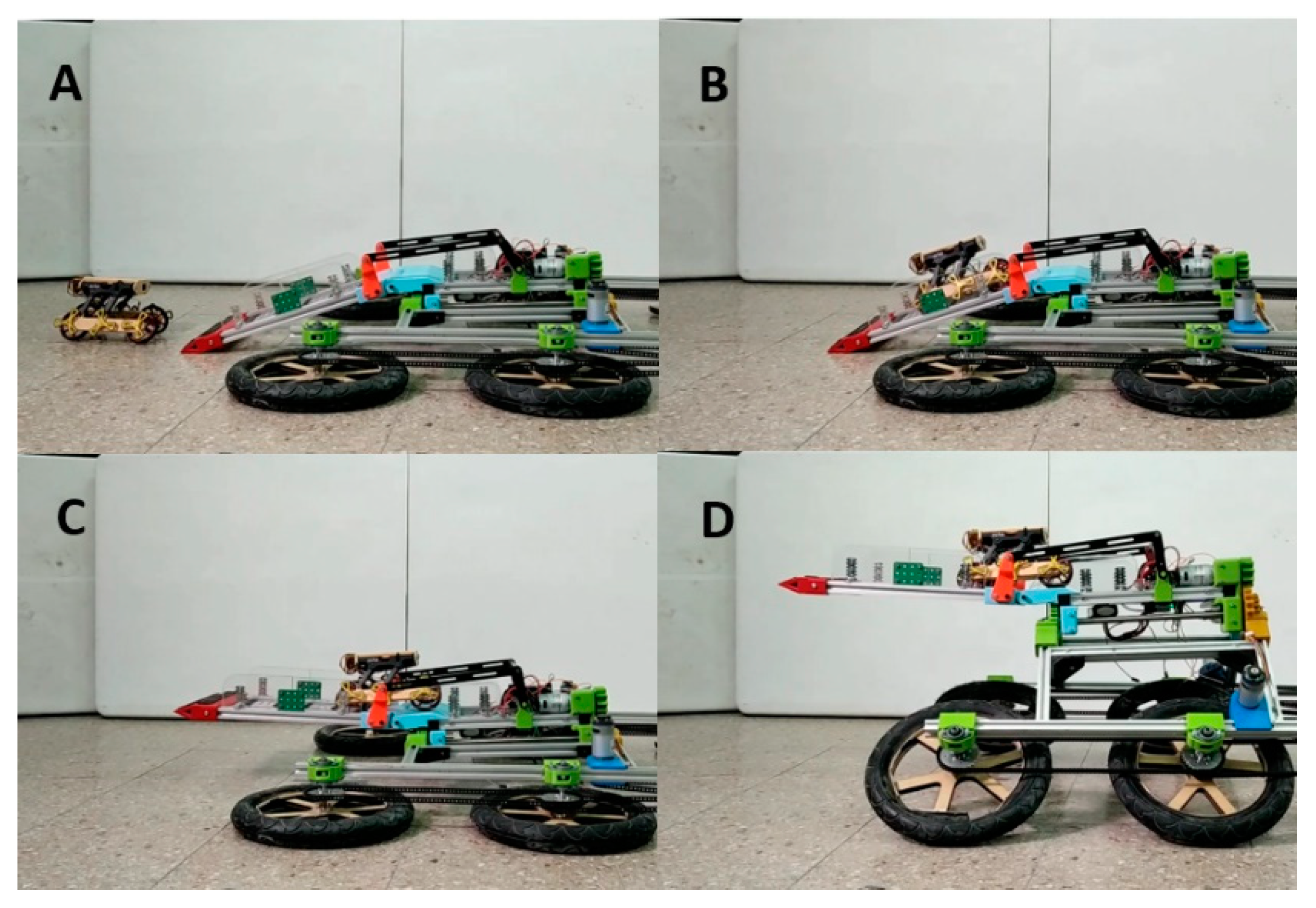
The BSTAR and RSTAR can be preprogrammed to perform a set of sequences for specific tasks. We preprogrammed to automatically lower its body and tail to dispatch or recover RSTAR, while the RSTAR is preprogrammed to climb on (Figure 17) or off the ramp (Figure 18) of BSTAR. Note that in order for the RSTAR to climb onto the BSTAR, the two robots must be aligned (see video in Supplementary Materials).
4.3. Energy Requirements and Recharging
4.3.1. Energy Consumption
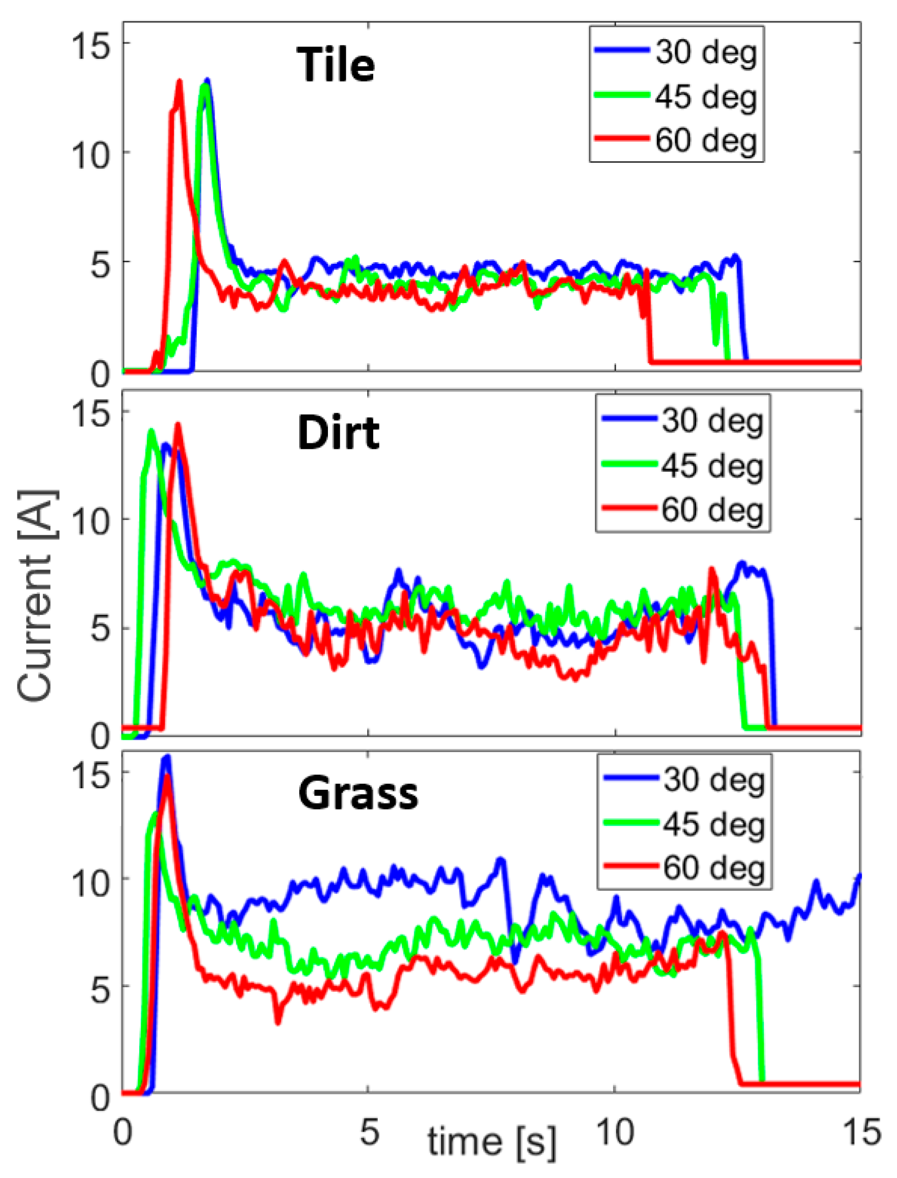
Figure 19 shows the current consumption of the BSTAR at its maximum speed as recorded by its ESC controller. The experiment was performed over three different surfaces while running the robot at its full speed with three different sprawl angles. After accelerating, the robot was run for 10 m in each experiment while the current was measured.
The average results of the experiments (not including the acceleration) are summarized in Table 2. The average speed was measured by processing the video of the experiment and the power consumption relative to the nominal battery voltage (7.4 Volts). The COT (or specific resistance) is the power consumption divided by the product of the speed multiplied by the weight of the robot. As expected, the COT was lower on the tiles than over dirt and higher over grass. While a low sprawl was useful in climbing uphill and overcoming obstacles, it resulted in significantly higher COT due to increased friction of the wheels with the surface.
4.3.2. Recharging RSTAR
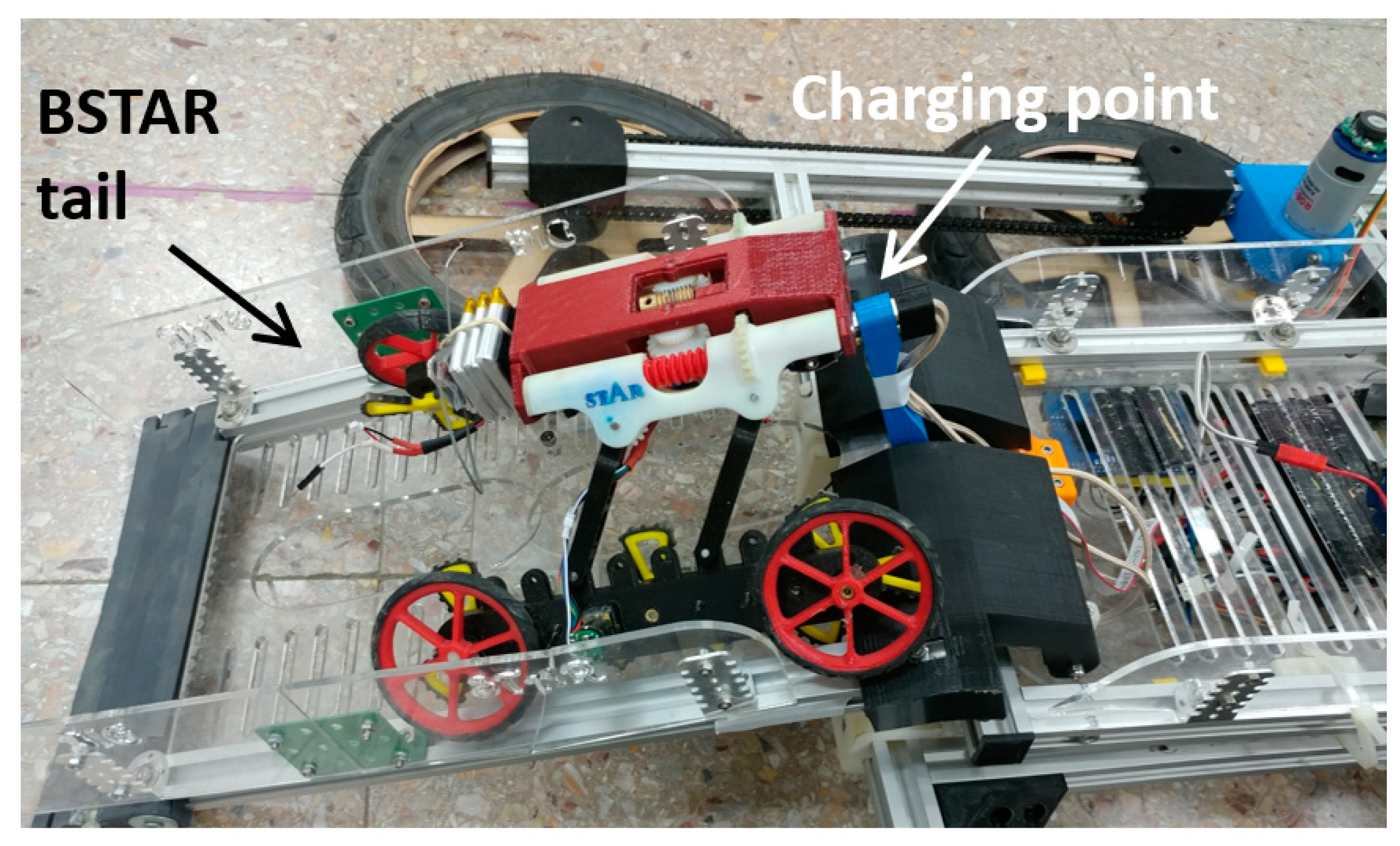
As in Nature, the parent robot can also provide its child robot with energy. A recharging point can be attached to the tail of the BSTAR to recharge the battery of the RSTAR. Because the charging point is in the center of the tail and the RSTAR is in contact with both walls of the tail, the docking is very simple. The RSTAR simply has to approach the charging point and adjust its height to plug to its connector into the charging point magnetically (Figure 20 and video).
5. Conclusions
This paper presented the design of a bioinspired wheeled vehicle, the Big STAR. The BSTAR incorporates multiple bioinspired features which substantially improve its performance. The sprawling mechanism, inspired by cockroaches, allows it to change its dynamics and external geometry. The parent BSTAR is fitted with a tail which is used as a ramp to carry, deploy and retrieve the child RSTAR. The BSTAR can also provide its child robot with energy while it is onboard. The BSTAR is nearly seven times larger than the original version of the STAR robot. Its size allows it to overcome larger obstacles and traverse rough terrains to carry large payloads, while the smaller robot can sneak underneath obstacles and between cracks and has a lower energy consumption in terms of distance travelled. The collaboration between the two robots proved extremely efficient in that it enabled them to reach areas that would have been inaccessible to each separately.
By sprawling down and lowering its tail, the BSTAR can contact the ground and allow the RSTAR to climb onto its body. Besides carrying it at higher speeds and over rough terrains, the BSTAR can deploy the RSTAR on fences that are up to 88 cm high. The BSTAR can carry up to three RSTARs on top of its body and tail.
The collaboration between the two robots can also increase their working range and scouting area in that the BSTAR can be used as a charging point for the RSTAR. The current battery of BSTAR is 20 times larger than the smaller robot. The battery can be further enlarged as necessary since the BSTAR can carry a payload of up to 5 kg (enough to increase its battery size by five-fold). The RSTAR batteries can easily be connected to the BSTAR as it climbs into the actuated tail.
Our future goals are to develop a locomotion planning algorithm for the robot and a climbing strategy that allows the smaller STAR to climb onto its parent robot.
Supplementary Materials
The following are available online at https://www.mdpi.com/2076-3417/10/24/8767/s1.
Author Contributions
D.Y. and D.Z. provided the research ideas and the theoretical analysis and wrote the paper; Design and experiments, D.Y., L.Y., O.I., and D.Z.; Analysis, D.Y., and D.Z.; Supervision, D.Z. All authors have read and agreed to the published version of the manuscript.
Funding
This research was partially funded by the ABC robotics Center and the Pearlstone Center for aeronautical research.
Conflicts of Interest
The authors claim that there is no conflict of interest regarding the publication of this article.
Appendix A
Appendix A.1. Detailed View of the Sprawl Mechanism
The sprawl mechanism is 3D printed (FDM). We used metal axes for the gears and metal reinforcement bars to prevent the axes from bending. A potentiometer attached to one of the center spur gears is used to measure the actual value of the sprawl angle (see Figure A1).
Figure A1.
The detailed design of RSTAR’s sprawl.

Appendix A.2. Design Improvements of the BSTAR Robot
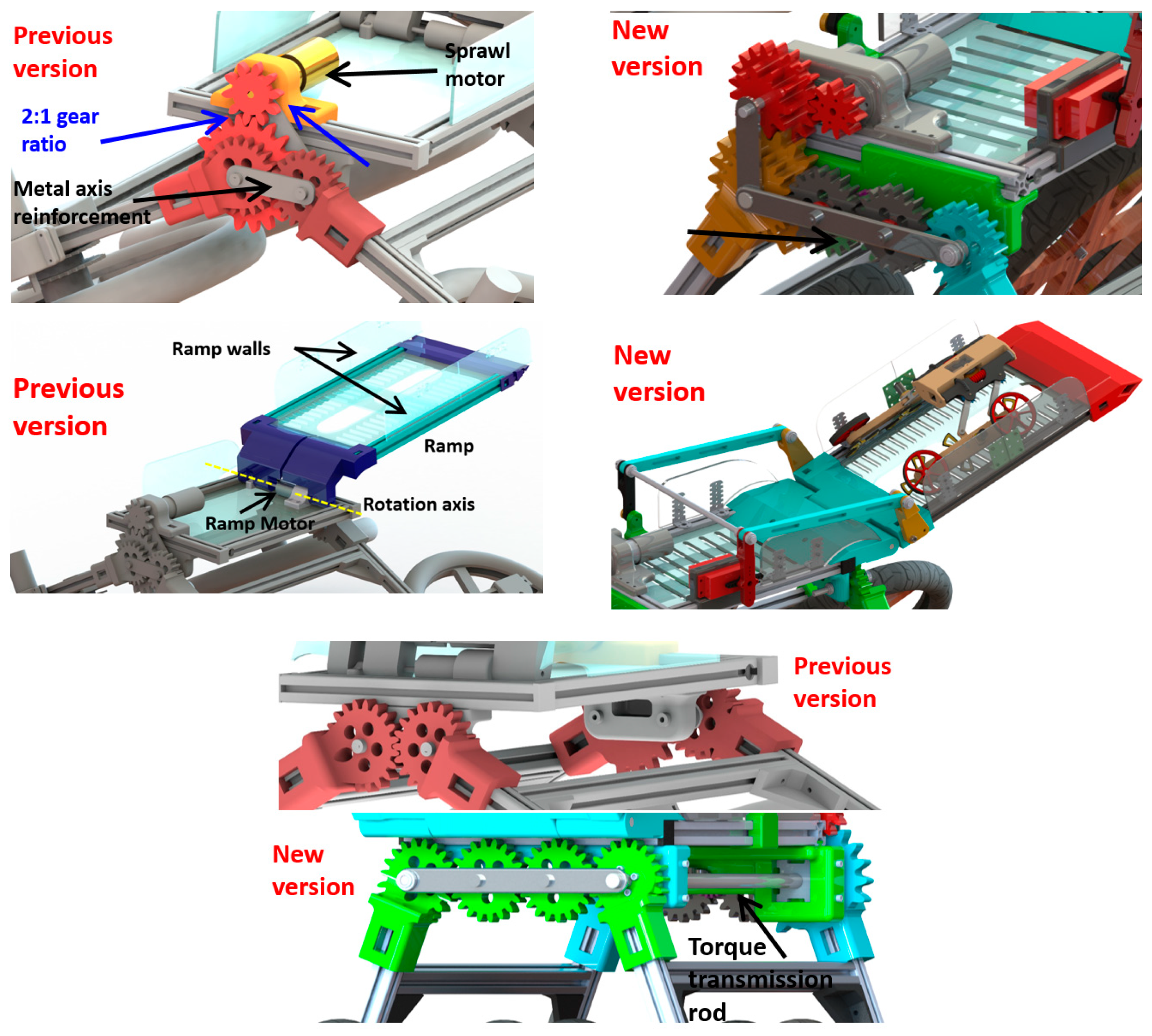
After developing the first version of BSTAR and testing it outdoors (see video in Supplementary Materials), we made a number of design improvements to the sprawl mechanism and ramp (see Figure A2).
Figure A2.
Comparison of the previous and new versions of the sprawl (Top and Center) and the ramp mechanisms (Bottom).
Figure A2.
Comparison of the previous and new versions of the sprawl (Top and Center) and the ramp mechanisms (Bottom).

Appendix A.3. Sprawl Mechanism Improvements
The motor of the sprawl mechanism was chosen as a function of its torque output (ability to generate enough torque to lift the robot). However, its gear box broke often. The original sprawl mechanism of the BSTAR had a 2:1 gear ratio. A second level of gears was added in the newer version to increase the gear ratio by a factor of 2 (4:1). Metal reinforcement rods which align the axes of the gears are also used in the newer version to maintain the gears in their position and reduce their axis bending.
Appendix A.4. Torque Transmission
To improve the transmission of the torque to the back of the robot and reduce the bending of the legs, we attached a steel rod with a 12 mm diameter to the front and back gears to distribute the sprawl torque equally between the front and back of the robot. The rod successfully reduced the bending of the legs of the robot and diminished the forces acting on the front sprawl mechanism gears.
Appendix A.5. Ramp Design
In the initial design, the ramp motor was aligned with the rotation axis of the ramp. Although the motor supplied enough torque for ramp actuation (lifting and lowering the ramp while the RSTAR was onboard), it was not sufficiently stable since vibrations caused the ramp to slip on multiple occasions from its rotation axis. This happened primarily when the robot was driven outdoors on uneven surfaces.
References
- Morrey, J.; Larribrecht, B.; Horchler, A.; Ritzmann, R.; Quinn, R. Highly mobile and robust small quadruped robots. In Proceedings of the 2003 IEEE/RSJ International Conference on Intelligent Robots and Systems (IROS 2003), Las Vegas, NV, USA, 27–31 October 2003; pp. 82–87. [Google Scholar]
- Hoover, A.M.; Burden, S.; Fu, X.Y.; Sastry, S.S.; Fearing, R.S. Bio-inspired design and dynamic maneuverability of a minimally actuated six-legged robot. In Proceedings of the 3rd IEEE RAS and EMBS International Conference on Biomedical Robotics and Biomechatronics, Tokyo, Japan, 26–29 September 2010; pp. 869–873. [Google Scholar]
- Birkmeyer, P.; Peterson, K.; Fearing, R.S. DASH: A dynamic 16g hexapedal robot. In Proceedings of the The 2009 IEEE/RSJ International Conference on Intelligent RObots and Systems, St. Louis, MO, USA, 11–15 October 2009; pp. 2683–2689. [Google Scholar]
- Kim, S.; Clark, J.E.; Cutkosky, M.R. iSprawl: Design and Tuning for High-speed Autonomous Open-loop Running. Int. J. Robot. Res. 2006, 25, 903–912. [Google Scholar] [CrossRef]
- Pullin, A.; Kohut, N.; Zarrouk, D.; Fearing, R.S. Dynamic turning of 13 cm robot comparing tail and differential drive. In Proceedings of the IEEE International Conference on Robotics and Automation (ICRA), St. Paul, MN, USA, 14–19 May 2012; pp. 5083–5093. [Google Scholar]
- Galloway, K.C.; Haynes, G.C.; Ilhan, B.D.; Johnson, A.M.; Knopf, R.; Lynch, G.; Plotnick, B.; White, M.; Koditschek, D.E. X-RHex: A Highly Mobile Hexapedal Robot for Sensorimotor Tasks; Technical Report; University of Pennsylvania: Philadelphia, PA, USA, 2010. [Google Scholar]
- Cham, J.G.; Bailey, S.A.; Clark, J.E.; Full, R.J.; Cutkosky, M.R. Fast and Robust: Hexapedal Robots via Shape Deposition Manufacturing. Int. J. Robot. Res. 2002, 21, 869–882. [Google Scholar] [CrossRef]
- Kohut, N.; Pullin, A.; Haldane, D.W.; Zarrouk, D.; Fearing, R.S. Precise dynamic turning of a 10 cm legged robot on a low friction surface using a tail. In Proceedings of the 2013 IEEE International Conference on Robotics and Automation, Karlsruhe, Germany, 6–10 May 2013; pp. 3299–3306. [Google Scholar]
- Zarrouk, D.; Pullin, A.; Kohut, N.; Fearing, R.S. STAR, a sprawl tuned autonomous robot. In Proceedings of the 2013 IEEE International Conference on Robotics and Automation, Karlsruhe, Germany, 6–10 May 2013; pp. 20–25. [Google Scholar]
- Karidis, P.K.; Zarrouk, D.; Poulakakis, I.; Fearing, R.S.; Tanner, H.G. Planning with the STAR(s). In Proceedings of the IEEE/RSJ International Conference on Intelligent Robots and Systems, Chicago, IL USA, 14–18 September 2014; pp. 3033–3038. [Google Scholar]
- Zarrouk, D.; Fearing, R.S. Controlled In-Plane Locomotion of a Hexapod Using a Single Actuator. IEEE Trans. Robot. 2015, 31, 157–167. [Google Scholar] [CrossRef]
- Zarrouk, D.; Yehezkel, L. Rising STAR: A Highly Reconfigurable Sprawl Tuned Robot. IEEE Robot. Autom. Lett. 2018, 3, 1888–1895. [Google Scholar] [CrossRef]
- Karras, J.T.; Fuller, C.L.; Carpenter, K.C.; Buscicchio, A.; Mckeeby, D.; Norman, C.J.; Parcheta, C.E.; Davydychev, I.; Fearing, R.S. Pop-up mars rover with textile-enhanced rigid-flex PCB body. In Proceedings of the IEEE International Conference on Robotics and Automation, Marina Bay Sands, Singapore, 28 May–3 June 2017; pp. 5459–5466. [Google Scholar]
- Kim, Y.S.; Jung, G.P.; Kim, H.; Cho, K.J.; Chu, C.N. Wheel Transformer: A Wheel-Leg Hybrid Robot with Passive Transformable Wheels. IEEE Trans. Robot. 2014, 30, 1487–1498. [Google Scholar] [CrossRef]
- Spenko, M.J.; Haynes, G.C.; Saunders, J.A.; Cutkosky, M.R.; Rizzi, A.A.; Full, R.J.; Koditschek, D.E. Biologically inspired climbing with a hexapedal robot. J. Field Robot. 2008, 25, 223–242. [Google Scholar] [CrossRef] [Green Version]
- Tan, N.; Mohan, R.E.; Elangovan, K. Scorpio: A Biomimetic Reconfigurable Rolling-Crawling Robot. Int. J. Adv. Robot. Syst. 2016, 13, 1729881416658180. [Google Scholar] [CrossRef]
- Tian, Y.; Zhang, D.; Yao, Y.A.; Kong, X.; Li, Y. A reconfigurable multi-mode mobile parallel robot. Mech. Mach. Theory 2017, 11, 39–65. [Google Scholar] [CrossRef]
- Ding, W.; Detert, T.; Corves, B.; Yao, Y.A. Reconbot: A Reconfigurable Rescue Robot Composed of Serial-Parallel Hybrid Upper Humanoid Body and Track Mobile Platform. In New Advances in Mechanisms, Mechanical Transmissions and Robotics Mechanisms and Machine Science; Springer: Cham, Switzerland, 2016; pp. 241–249. [Google Scholar]
- Chen, S.C.; Huang, K.J.; Chen, W.H.; Shen, S.Y.; Li, C.H.; Lin, P.C. Quattroped: A Leg--Wheel Transformable Robot. IEEE/ASME Trans. Mechatron. 2014, 19, 730–742. [Google Scholar] [CrossRef]
- Sun, Y.; Ma, S. Decoupled kinematic control of terrestrial locomotion for an ePaddle-based reconfigurable amphibious robot. In Proceedings of the IEEE International Conference on Robotics and Automation, Shanghai, China, 9–13 May 2011; pp. 1223–1228. [Google Scholar]
- Khan, M.T.; Qadir, M.U.; Nasir, F.; Silva, C.W.D. A framework for a fault tolerant multi-robot system. In Proceedings of the 10th International Conference on Computer Science & Education, Cambridge, UK, 22–24 June 2015; pp. 197–201. [Google Scholar]
- Fong, T.; Grange, S.; Thorpe, C.; Baur, C. Multi-robot remote driving with collaborative control. In Proceedings of the 10th IEEE International Workshop on Robot and Human Interactive Communication, Bordeaux, Paris, France, 18–21 September 2001; pp. 669–704. [Google Scholar]
- Wagner, G.; Choset, H. Subdimensional expansion for multirobot path planning. Artif. Intell. 2015, 219, 1–24. [Google Scholar] [CrossRef]
- Shnaps, I.; Rimon, E. Online Coverage by a Tethered Autonomous Mobile Robot in Planar Unknown Environments. IEEE Trans. Robot. 2014, 30, 966–974. [Google Scholar] [CrossRef]
- Min, B.C.; Matson, E.T.; Jung, J.W. Active Antenna Tracking System with Directional Antennas for Enhancing Wireless Communication Capabilities of a Networked Robotic System. J. Field Robot. 2015, 33, 391–406. [Google Scholar] [CrossRef] [Green Version]
- Vargas, A.M.; Mizuuchi, K.; Endo, D.; Rohmer, E.; Nagatani, K.; Yoshida, K. Development of a Networked Robotic System for Disaster Mitigation, Navigation System based on 3D Geometry Acquisition. In Proceedings of the IEEE/RSJ International Conference on Intelligent Robots and Systems, Beijing, China, 9–15 October 2006; pp. 4821–4826. [Google Scholar]
- Yang, Y.; Xu, G.; Wu, X.; Feng, H.; Xu, Y. Parent-child robot system for rescue missions. In Proceedings of the IEEE International Conference on Robotics and Biomimetics, Guilin, China, 18–22 December 2009; pp. 1427–1432. [Google Scholar]
- Huang, B.; Li, M.; Sun, L. The Research of a parent-children type robot system. In Proceedings of the IEEE International Conference on Robotics and Biomimetics, Kunming, China, 17–20 December 2006; pp. 977–981. [Google Scholar]
- Schmitt, J.; Holmes, P. Mechanical models for insect locomotion: Dynamics and stability in the horizontal plane I. Theory. Biol. Cyber. 2000, 83, 501–515. [Google Scholar] [CrossRef] [PubMed]
- Schmitt, J.; Holmes, P. Mechanical models for insect locomotion: Dynamics and stability in the horizontal plane II. Appl. Biol. Cyber. 2000, 83, 517–527. [Google Scholar] [CrossRef] [PubMed]
- Meiri, N.; Zarrouk, D. Flying STAR, a Hybrid Crawling and Flying Sprawl Tuned Robot. In Proceedings of the International Conference on Robotics and Automation, Montreal, QC, Canada, 20–24 December 2019; pp. 5302–5308. [Google Scholar]
Figure 1.
The parent BSTAR robot can carry RSTAR robots and is capable of deploying and recovering them using its actuated tail. The size ratio of the characteristic lengths of the BSTAR to the RSTAR is 6:1.
Figure 1.
The parent BSTAR robot can carry RSTAR robots and is capable of deploying and recovering them using its actuated tail. The size ratio of the characteristic lengths of the BSTAR to the RSTAR is 6:1.

Figure 2.
The dimensions of the BSTAR, the parent robot. Top—front view; Bottom—side view.

Figure 3.
The dimensions of the RSTAR, the child robot. Top—front view; Bottom—side view.

Figure 4.
The rising LTAR carrying three RSTAR robots, one on its main body and two on the tail.

Figure 5.
The gear transmission of the driving wheels.

Figure 6.
The sprawl mechanism. Front and back views.

Figure 7.
The ramp is actuated by a motor aligned with its rotation axis.

Figure 8.
The control system of the robot is based on an Arduino Uno controller and two RobotClaw ECS controllers.
Figure 8.
The control system of the robot is based on an Arduino Uno controller and two RobotClaw ECS controllers.

Figure 9.
The Rising STAR climbs onto the tail and secures itself by pushing its wheels against the tail housing.
Figure 9.
The Rising STAR climbs onto the tail and secures itself by pushing its wheels against the tail housing.

Figure 10.
The torques that must be applied by the sprawl and four bar extension mechanism (FBEM) joints to maintain a normal force of 4.9 N to the walls to climb vertically.
Figure 10.
The torques that must be applied by the sprawl and four bar extension mechanism (FBEM) joints to maintain a normal force of 4.9 N to the walls to climb vertically.

Figure 11.
The width and height of obstacles that the RSTAR and BSTAR can pass between or underneath. (A) The RSTAR passing between obstacles. (B) The RSTAR squeezing underneath and obstacle. (C) The BSTAR passing between obstacles. (D) The BSTAR squeezing underneath an obstacle.
Figure 11.
The width and height of obstacles that the RSTAR and BSTAR can pass between or underneath. (A) The RSTAR passing between obstacles. (B) The RSTAR squeezing underneath and obstacle. (C) The BSTAR passing between obstacles. (D) The BSTAR squeezing underneath an obstacle.

Figure 12.
The maximum height of obstacles the robot can overcome. (A) BSTAR. (B) RSTAR. (C) RSTAR getting a boost up from BSTAR.
Figure 12.
The maximum height of obstacles the robot can overcome. (A) BSTAR. (B) RSTAR. (C) RSTAR getting a boost up from BSTAR.

Figure 13.
Flowchart of the obstacles that the collaborating parent and child robots can overcome.

Figure 14.
The area that the robots can scout, where the BSTAR acts as a recharging platform for the RSTAR robots. S0 is the recharging point, Si is the stop before returning to recharge.
Figure 14.
The area that the robots can scout, where the BSTAR acts as a recharging platform for the RSTAR robots. S0 is the recharging point, Si is the stop before returning to recharge.

Figure 15.
The BSTAR travelling over challenging terrains including cracks (A), dirt and vegetation (B), gravel (C), and stones (D) (see video in Supplementary Materials).
Figure 15.
The BSTAR travelling over challenging terrains including cracks (A), dirt and vegetation (B), gravel (C), and stones (D) (see video in Supplementary Materials).

Figure 16.
The BSTAR recovering RSTAR (A to B), carrying it on its tail (C) and dispatching it over a fence (D) (see video in Supplementary Materials).
Figure 16.
The BSTAR recovering RSTAR (A to B), carrying it on its tail (C) and dispatching it over a fence (D) (see video in Supplementary Materials).

Figure 17.
The BSTAR automatically recovering RSTAR (see video in Supplementary Materials). Starting in (A), the RSTAR climbs on the ramp (B) while the BSTAR lifts its tail (C) and body (D).
Figure 17.
The BSTAR automatically recovering RSTAR (see video in Supplementary Materials). Starting in (A), the RSTAR climbs on the ramp (B) while the BSTAR lifts its tail (C) and body (D).

Figure 18.
The BSTAR automatically deploying RSTAR (see video in Supplementary Materials). Starting in (A), the BSTAR lowers its body (B), and then its tail (C) to dispatch the RSTAR (D).
Figure 18.
The BSTAR automatically deploying RSTAR (see video in Supplementary Materials). Starting in (A), the BSTAR lowers its body (B), and then its tail (C) to dispatch the RSTAR (D).

Figure 19.
The current consumption of BSTAR over three different surfaces (tiles, dirt and grass) for three sprawl angles (30, 45 and 60 degrees) at its maximum output speed.
Figure 19.
The current consumption of BSTAR over three different surfaces (tiles, dirt and grass) for three sprawl angles (30, 45 and 60 degrees) at its maximum output speed.

Figure 20.
The RSTAR connecting to the charging point of the BSTAR (see video in Supplementary Materials).
Figure 20.
The RSTAR connecting to the charging point of the BSTAR (see video in Supplementary Materials).


Table 1.
The main specifications of RSTAR and BSTAR.
| Robot Characteristics | RSTAR | BSTAR |
|---|---|---|
| Characteristic length | LR = 14.5 cm | LB = 82.5 cm |
| Wheel/whegs radius | rR = 2.8 cm | rB = 15.5 cm |
| Minimum width | Min(wR) = 8.9 cm | Min(wB) = 32.5 cm |
| Maximum width | Max(wR) = 28.5 cm | Max(wB) = 90.2 cm |
| Minimum height | Min(hR) = 3.5 cm | Min(hB) = 21 cm |
| Maximum height | Max(hR) = 12.8 cm | Max(hB) = 50.3 cm |
| Robot mass | mR = 0.38 kg | mB = 9.8 kg |
| Battery (Lipo) | 800 mAh | 2 × 5200 mAh |
| Mass | 0.032 kg | 0.72 kg |
| Voltage | 7.4 V | 11.1 V |
| Energy | 21.3 kJ | 415.6 kJ |
| Working range | dR = 5.12 km | dB = 11.7 km |
| Maximum speed | VR = 0.8 m/s | VB = 1.4 m/s |
| COT (specific resistance) | 1.12 | 0.37 |
| Safe Payload | 0.2 kg | 5 kg |
Table 2.
The power requirements of BSTAR.
| Surface | Sprawl | Speed [m/s] | Current [A] | Power [W] | COT |
|---|---|---|---|---|---|
| Tile | 30 | 1.13 | 4.57 | 33.8 | 0.299 |
| Tile | 45 | 1.17 | 4.31 | 31.9 | 0.272 |
| Tile | 60 | 1.25 | 3.86 | 27.8 | 0.221 |
| Dirt | 30 | 1.05 | 5.16 | 38.2 | 0.333 |
| Dirt | 45 | 1.05 | 6.30 | 46.6 | 0.443 |
| Dirt | 60 | 1.05 | 5.23 | 38.6 | 0.367 |
| Grass | 30 | 0.8 | 9.66 | 71.5 | 0.892 |
| Grass | 45 | 1.03 | 6.69 | 49.5 | 0.477 |
| Grass | 60 | 1.11 | 5.07 | 37.5 | 0.337 |
Publisher’s Note: MDPI stays neutral with regard to jurisdictional claims in published maps and institutional affiliations. |
© 2020 by the authors. Licensee MDPI, Basel, Switzerland. This article is an open access article distributed under the terms and conditions of the Creative Commons Attribution (CC BY) license (http://creativecommons.org/licenses/by/4.0/).
Share and Cite
MDPI and ACS Style
Yacoby, D.; Yehezkel, L.; Inbar, O.; Zarrouk, D. Design and Modeling of a Parent Big STAR Robot Platform That Carries a Child RSTAR. Appl. Sci. 2020, 10, 8767. https://doi.org/10.3390/app10248767
AMA Style
Yacoby D, Yehezkel L, Inbar O, Zarrouk D. Design and Modeling of a Parent Big STAR Robot Platform That Carries a Child RSTAR. Applied Sciences. 2020; 10(24):8767. https://doi.org/10.3390/app10248767
Chicago/Turabian StyleYacoby, Daniel, Liran Yehezkel, Ori Inbar, and David Zarrouk. 2020. "Design and Modeling of a Parent Big STAR Robot Platform That Carries a Child RSTAR" Applied Sciences 10, no. 24: 8767. https://doi.org/10.3390/app10248767
Note that from the first issue of 2016, this journal uses article numbers instead of page numbers. See further details here.